Next stage Sure3116 has ~30k inputimpedance and 26dB gain, remove R16 there and inputimpedance becomes ~60k with 20dB gain, still I would not increase potvalue to 100k, maybe you need an aditional tubebuffer for Sure3116 ?????
A temporary senior moment caused me to forget that the circuit ends with a volume control. I was referring to the output from the SRPP.
There are some circuits which are so bad in such obvious ways that some people begin to assume that they must be really good in some new, deep way which ordinary engineers cannot understand.
There are some circuits which are so bad in such obvious ways that some people begin to assume that they must be really good in some new, deep way which ordinary engineers cannot understand.
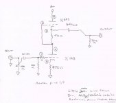
The circuit shown in post 18 is a simple balanced SRPP, so it will have voltage gain equal to half the valve mu. In many cases this will be far too much gain. The output impedance will be lowish (for a valve circuit) but possibly still higher than the output impedance of the original source!
Do you mean noise or hum? Noise could come from an oscillating valve, so try adding grid stoppers. Hum could come from poor heater-cathode insulation (unless it uses DC heaters - I'm not sure).
I suspect that the various Little Bear items are sold as lifestyle choices rather than serious audio items. Use whatever caps make you happy. Audio engineering considerations would suggest that the input cap ought to have a somewhat smaller value, as an LF rolloff at around 1.5Hz could let in a lot of unwanted subsonics.
So, is there a way to drive two Sure TPA3116 amps (around 30k input impedance) on the output of this supposedly SRPP preamp?
It has two rectifiers, one 6Z4 and other with diode bridge.
I believe 6N3 heaters are on DC, but 6Z4 heater seems to be on AC...
Noise I'm getting is kind of electrical hum and low hiss, but only audible when I turn 50k pot around half turn and above... though, situation gets better when tubes are ON after ten minutes... then, there is only little hiss and hint of electric noise...
As potentiometer range is useless (too loud even before 9h setting), I wonder what I could do about it...
Those 6N3 "preamps" were recomended by many for use with D-class TI amps...
What capacitance do You recomend for in and out signal decoupling?
I don't have problems with high and medium tones with my combo, only low end is pretty shallow without sub...
TIA and keep in mind that I am new to all this, be gentle 😉
If you want to reduce the noise, you need a DC heater for all tubes ( use eg. a LM317 and set the required voltage, most the time 6,3V for regular tubes ), also make sure that the DC heater power supply has a ground connection with the common ground.
If you can still hear a hum, you need to improve the power supply too ( use eg. bigger capacitors and some C R C networks. Check eg PSUDII to get a idea about how to build a power supply ).
Best regards,
If you can still hear a hum, you need to improve the power supply too ( use eg. bigger capacitors and some C R C networks. Check eg PSUDII to get a idea about how to build a power supply ).
Best regards,
You probably don't need a line stage at all. Just put a volume pot in a box. This will drive an output (cable plus power amp input) just as well as the Little Bear does, but with no added noise or hum and no excessive gain.robertinjo said:As potentiometer range is useless (too loud even before 9h setting), I wonder what I could do about it...
Don't believe everything you read on the internet. Almost all modern systems need no line stage. If the power amp has a nasty non-linear input impedance then you need a buffer with no gain but a low output impedance (i.e. a follower, such as an opamp) not a preamp with gain and a high output impedance.Those 6N3 "preamps" were recomended by many for use with D-class TI amps...
Coupling, not decoupling. Input I would go to 0.47uF or even 0.22uF. Output depends on what it is driving. If 15k then 1uF will give you a 10.6Hz rolloff. May be OK, or try 2.2uF if you have particularly large speakers and a large room so true bass is possible.What capacitance do You recomend for in and out signal decoupling?
To deal with your noise problem you need to diagnose its cause. Difficult to do without a scope.
Sure provides this for the stereo version:
Input Sensitivity (V)
-
-
0.74
-
Input Impedance (Kohm)
-
-
22
-
Gain (dB)
TPA3116
25
26
27
On Sure3116 I also measure 17.5nF between inputs RCA signal and shield, without cable attached, directly on Sure pcb. In signal to inputpin tpachip there is a ceramic couplingcap 2uF (probably rated 2.2uF). You have two highpass filters after each other, one in LB output and one on Sure input. I think the outputimpedance LB as you draw will rolloff treble, but more knowledge with other posters here. Some chinese sellers say your LB amplifies 20x, rusian tube you put in might be even stronger, 740mv needed for max output it seems, doesn't seem real practical.
If the amp really has 17.5nF as input capacitance, and the LB circuit in post 18 is correct, then there is no chance that it will work OK. A 50k volume pot has a maximum source impedance of 12.5k. 12.5k and 17.5nF give a rolloff from 730Hz - no treble at all! Fortunately, the unnecessary gain of the LB means that you will mainly have the volume pot at a low setting so the HF rolloff won't be so bad.
If the circuit in post 18 is correct, then the LB is essentially an unwanted gain block followed by a 'passive preamp'. Difficult to think of what situation might require such an item in the signal chain.
If the circuit in post 18 is correct, then the LB is essentially an unwanted gain block followed by a 'passive preamp'. Difficult to think of what situation might require such an item in the signal chain.
Rca's inputsignal to shield(gnd) on pcb measures 17.5nF when pcb is not powered or connected to source, 30nF when pcb is powered but still unconnected to source. Silkscreen labels some components TVS and RV on Sure input(protection?), maybe that capacity disappears with signal?? Other 3116 ampboard with just the datasheet components measure around 100pF (that could be parasitic but not sure how off/accurate my DMM is for pF, nF's are reasonably accurate)
Signals rarely make capacitance disappear. Being powered can increase or reduce capacitance; the value which matters is the powered one. 30nF seems an awfully large input capacitance - are you sure? Remember that DMM can be confused by parallel resistance. What input capacitance would you expect, given the circuit diagram etc.?
Well Wima 5% fkp 47pF measures 62pF on dmm🙂 standard circuit datasheet on another ampboard 90-100pF (just a series couplingcapacitor to chip). Wima 100nF measures 102.0 nF and Sure3116 30nF only connected to power (on), that has TVS between signal and ground and next a RV between signal and ground and then the series coupling capacitor. Maybe the dmm goes wrong with the tvs double? diode or the rv varistor?, I don't know what capacity these would normally have, but I would guess also 100pF each ??? so then if anything I might expect 250pF-300pF total 🙂
Printed names next to the components are tvs1 and rv1 and tvs2 and rv2, I don't know what they are, the tvs looks like a transistor but could be a diode, the rv looks like a dark resistor with a few lines black and white across but could be a diode too, surface mount parts both, I guess (surge) protection, don't know why double protection would be used, do know 22k inputimpedance is lower than ~30k inputimpedance for datasheet implementation, that decrease also caused by those two parts I would say, like there also seems to be a capacitance to ground, so maybe the little striped thingy is a kind of capacitor ?

Update: Got the NOS Telefunken 75/75 12ax7 tubes in and been playing them the last 4 nights. I now have so much more bass that I had to pull the speakers away from the back wall. It was way to big and boomy sounding. Now its much more nicely balanced when I gave the speakers more breathing room. These Telefunken definitely gave me a much wider and deeper sound stage. Smoot her and detailed presentation than before. I havn't switched back to the chinese tubes yet to compare again to determine exactly what has changed besides the obvious more bass and weight.
Ok, I got the schematic and I added notes and attached it to this post. Thank you Mr Kelashnain from the Vinyl Engine for drawing it for me. I circled each of the resistors and capacitors that is in the direct audio signal path. I didn't circle any of the comonants that ended at a ground. I don't know if exchanging those out for much higher quality componants would make a differance since it is just a ground? Hope someone that knows electronics can comment.
As you can see on the schematic, 3 of the capacitors are the WIMA quare caps. If I swap them out for something magnatudes better like Mundorf Paper n Oil gold does it matter they are not square but they are tubular with leads coming out each end? I dont know why they make caps square shapped and it there is a very good reason for that.
Another question, the traces to B+1, B+2, and B+3. Is that important? I dont know what they are for but if it is then I should swap out those resistors as well.
Last, the only capacitor in the signal path that is normal shape is the 4700uF 35v cap. For some reason the schematic had it marked as "330pf Board Markings and 300Pf Stuffer" But on my Little Bear circuit board I have a single 4700uF 35v cap. Can anyone explain that?
her and detailed presentation than before. I havn't switched back to the chinese tubes yet to compare again to determine exactly what has changed besides the obvious more bass and weight.Ok, I got the schematic and I added notes and attached it to this post. Thank you Mr Kelashnain from the Vinyl Engine for drawing it for me. I circled each of the resistors and capacitors that is in the direct audio signal path. I didn't circle any of the comonants that ended at a ground. I don't know if exchanging those out for much higher quality componants would make a differance since it is just a ground? Hope someone that knows electronics can comment.
As you can see on the schematic, 3 of the capacitors are the WIMA quare caps. If I swap them out for something magnatudes better like Mundorf Paper n Oil gold does it matter they are not square but they are tubular with leads coming out each end? I dont know why they make caps square shapped and it there is a very good reason for that.
Another question, the traces to B+1, B+2, and B+3. Is that important? I dont know what they are for but if it is then I should swap out those resistors as well.
Last, the only capacitor in the signal path that is normal shape is the 4700uF 35v cap. For some reason the schematic had it marked as "330pf Board Markings and 300Pf Stuffer" But on my Little Bear circuit board I have a single 4700uF 35v cap. Can anyone explain that?
Well, I guess im going to order the following componants and replace them. There are some big big sales going on right now and hope they have my values on stock. No one has replied if I should bother replacing the resistors that are only going to ground so I left them out.
Also, abot the power supply section. There is a big Rubycon Blackgate electrolytic sale going on right now. I figured that would be a big improvement of the standard Rubycons already in place? Or would the Rybcon "Gold Tone" models be better?
Capacitors x2: for left and right channels
4700uF 35v
0.47uF 400v
0.47uF 400v
0.1uF 400v
Resistors x2: for left and right channels
R24 - 220 ohm
R9 - 910 ohm
R8 - 3.3 meg
R7 - 100 ohm
R23 - 330k ohm
R15 - 330k ohm
- Status
- Not open for further replies.
- Home
- Amplifiers
- Tubes / Valves
- Little Bear P3 ?!?! opinions ?