
Me too, do you remember you showed me how to use Toshibas with Pumpkin and after hearing them I went back to the 610/9610 combo......🙂
bingo
though , that's (in first place) Mithrandir's passion - to teach us how to - with less/cheaper
though , that's (in first place) Mithrandir's passion - to teach us how to - with less/cheaper
Thanks Zen Mod for help to answer. I measured at output 2.8V, and used trim box to give soundcard at 0.4V. DC offset always readjust to 0Vdc after P3 change.
So did you gui think IRF610/9610 is good to used for this BA-3 pre?
So did you gui think IRF610/9610 is good to used for this BA-3 pre?
Last edited:
we were talking about  - completely different animal , comparing to BA3 FE
so , later one is example of fine balance of chosen gain values of first and second stage , giving specific set of THD harmonics
considering difference in gm between IRF and Toshiba mosfets (2S vs. 0.7S ) but mostly difference in Ugs for chosen Iq , it dictates accordingly increased drain resistances of first stage (if having IRF at output) ........ so it's having increased gain ..... same as second stage per se
result is increased gain , comparing to Toshibas in situ
it will certainly give different THD spectra ........ and only your ears can tell is it acceptable or not
with , there is overall (SUSY) feedback loop , resulting in said differences having much lesser influence on THD spectra , thus possible difference in sound
though , my Golden Eared German Friend is having much quicker trigger finger for those things .........
- completely different animal , comparing to BA3 FEso , later one is example of fine balance of chosen gain values of first and second stage , giving specific set of THD harmonics
considering difference in gm between IRF and Toshiba mosfets (2S vs. 0.7S ) but mostly difference in Ugs for chosen Iq , it dictates accordingly increased drain resistances of first stage (if having IRF at output) ........ so it's having increased gain ..... same as second stage per se
result is increased gain , comparing to Toshibas in situ
it will certainly give different THD spectra ........ and only your ears can tell is it acceptable or not
with
, there is overall (SUSY) feedback loop , resulting in said differences having much lesser influence on THD spectra , thus possible difference in soundthough , my Golden Eared German Friend is having much quicker trigger finger for those things .........
Last edited:
Thanks Zen Mod,
another question.
though some of you guy already mentioned about remove the output cap but not in details yet, and I really don't want the output cap at all. do you have a complete solution for that?
Thanks
another question.
though some of you guy already mentioned about remove the output cap but not in details yet, and I really don't want the output cap at all. do you have a complete solution for that?
Thanks
I wouldn't dare without some sort of servo
though , some iteration I tried , both in sims and in vivo , are too much Papalike ..... to even consider publishing them
besides , I'm always at least 3 years behind schedule , with homework he gave me
though , some iteration I tried , both in sims and in vivo , are too much Papalike ..... to even consider publishing them
besides , I'm always at least 3 years behind schedule , with homework he gave me
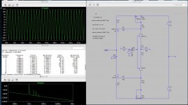
I played a bit with Spice and besides reducing the 330R load resistor even more to get lower gain, it seems possible to make the 100R from the J-Fet source node bigger to get lower gain, in my picture around 3.5.
I do not know if there is any drawback to do so……🙁
Zen Mod please….. 🙂
Indeed locking at the high k2 again, I suppose that the high k2 is coming from the IRFs and not directly from the circuit, that would explain the persistent k2.
first picture normal BA-3 and 100R
second picture with 350R source to ground resistor.
both with 1V input
Attachments
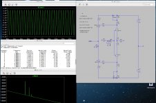
100R going up - there is nothing wrong with local degeneration
no ill effects on Jfet stage , in musician terms - just making input "harder"
compare input voltage with voltage at top of 100R ....... and observe how effective Ugs voltage (effective signal on Jfet gates) is going down in value when increasing that resistor
however , nothing wrong with K2 , as long we have proper rest of THD spectra
Last edited:
Dear all,
Any problem if I used the 10K pot? If yes how i can modify to used with 10K pot?
Thanks
Any problem if I used the 10K pot? If yes how i can modify to used with 10K pot?
Thanks
Vol pot usually comes between the Pre-amp and the Power Amp.
If the vol pot needs to drive a cable and other parasitic capacitances, then add a Buffer to the vol pot.
If the vol pot needs to drive a cable and other parasitic capacitances, then add a Buffer to the vol pot.
Yes, i always add volume pot at pre input. Not add between pre and pow. So thanks for your all kind reply.
adding attenuation before a gain stage is not the usual way to control volume.Yes, i always add volume pot at pre input. Not add between pre and pow. So thanks for your all kind reply.
This is done when there is a risk of overloading the gain stage where one source has a much higher output than what the gain stage is expected to normally pass/amplify.
adding attenuation before a gain stage is not the usual way to control volume.
.....
Attachments

Three comments from me.
1.) just say it rather than show a pic of what you are saying.
2.) stop abusing other Members.
3.) justify what you seem to think would be a good alternative.
1.) just say it rather than show a pic of what you are saying.
2.) stop abusing other Members.
3.) justify what you seem to think would be a good alternative.
Three comments from me.
1.) just say it rather than show a pic of what you are saying.
2.) stop abusing other Members.
3.) justify what you seem to think would be a good alternative.
next time don't write universal truth , with something covering minority of cases
of all things I know , most certain one is how small my knowledge is ; exactly because of that , I'm always leaving proper margin that I'm not having it 100% right
however , if you take 100 preamp schematics , you'll find at least in 85 of them arrangement of selector-attenuator-gain stage .
that's most common praxis , but certainly not best for all needs/cases
Thanks for your help all, guys.
it's not easy for me (or someone likes me) to understand detail all of schematic part. so all of your input always helpful.
i recalled in some other post someone mention 50K volume pot is best, but i just only have 10K volume pot on hand. so how the 50K volume pot is better than 10K volume pot? with this preamp, volume at output will better than volume of input? i used this preamp to driver F5 and ACA.
Thanks
Uy
I said "usually". I meant that and stand by my statement."adding attenuation before a gain stage is not the usual way to control volume."next time don't write universal truth , with something covering minority of cases
Just like me, I know and acknowledge my limitations.of all things I know , most certain one is how small my knowledge is ; exactly because of that , I'm always leaving proper margin that I'm not having it 100% right
I don't agree. The majority are vol pot >> Power Amp.however , if you take 100 preamp schematics , you'll find at least in 85 of them arrangement of selector-attenuator-gain stage .
If there is a gain stage, then that becomes
gain stage >> vol pot >> Power Amp.
In both of these cases a selector can be added at the input, resulting in:
selector >> vol pot >> Power Amp.
selector >> gain stage >> vol pot >> Power Amp.
This last could be rearranged to become:
gain stage >> selector >> vol pot >> Power Amp, which you will usually find for low level outputs.
that's most common praxis , but certainly not best for all needs/cases
Best practice is:
place the volume control as late in the audio stream as possible, this being just before the Power Amplifier. Even a Power Amplifier that is remote from the vol pot follows this "best practice".
Vol pot+Buffer >> cable >> Power Amp.
If you have seen some that break this "best practice", then you are looking at a poorly implemented arrangement.
I wonder what our Forum's article says?
http://www.diyaudio.com/forums/diyaudio-com-articles/186018-what-gain-structure.html
Last edited:
- Home
- Amplifiers
- Pass Labs
- BA-3 As Preamp