Hi
Possibly a hoary old topic, but I can't find anything on this specific PCB. If I'm wrong, and there's a 50 page thread out there, please point me to it.
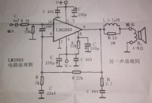
In a spirit of enquiry, I picked this PCB up from Ebay. It came with a kit of components including two LM3886TFs. Mostly no-name caps, except the input caps say 'Wima' on them. The PCB seems to mostly match the circuit diagram - one obvious exception is that the LM3886 share power supply decoupling caps.
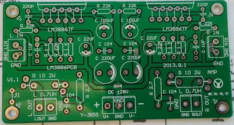
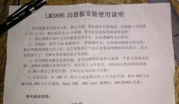
There's some no doubt very useful notes, but unfortunately I can't read them.

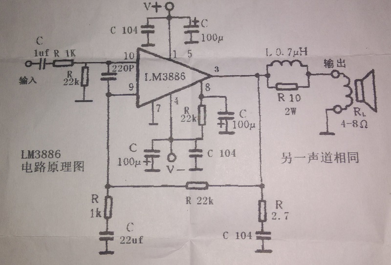
The circuit seems to be fairly close to the usual data sheet one.
Any thoughts on values, layout etc?
Cheers
John
Possibly a hoary old topic, but I can't find anything on this specific PCB. If I'm wrong, and there's a 50 page thread out there, please point me to it.
In a spirit of enquiry, I picked this PCB up from Ebay. It came with a kit of components including two LM3886TFs. Mostly no-name caps, except the input caps say 'Wima' on them. The PCB seems to mostly match the circuit diagram - one obvious exception is that the LM3886 share power supply decoupling caps.
There's some no doubt very useful notes, but unfortunately I can't read them.
The circuit seems to be fairly close to the usual data sheet one.
Any thoughts on values, layout etc?
Cheers
John
Attachments

I hate being the bearer of bad news but that PCB layout is pretty poor IMHO. And some of the component values are less than optimal, especially the power supply bypassing. I highly recommend you read the excellent analysis that TomChr did a few months ago, it's very thorough and informative. The link is here - Taming the LM3886 Chip Amplifier
Mike
Mike
The schematic is basically the Typical Application Schematic from the LM3886 data sheet. There's nothing wrong with it, but you can get better performance by changing a few values.
First off, add 22 kOhm in series with 47 pF across the 22 kOhm feedback resistor. This is to prevent excessive overshoot on the transient response caused by the noise gain compensation (220 pF cap across the amp inputs). Adding these components also reduce the peaking in the frequency response around 100 kHz where the noise gain compensation kicks in.
As Daniel writes, I suggest increasing the 22 uF capacitor to 220-1000 uF for lower THD at 20 Hz.
Also increase the two 220 uF supply decoupling capacitors to at least 1000 uF (National Semiconductor/TI recommends 470 uF per LM3886 in the data sheet).
Further, I suggest decreasing the 10 ohm resistor in the Thiele Network to 1.5 ohm to better dampen the ringing under capacitive load. Oh, and the eBay seller probably didn't bother to tell you how to wind the inductor... 15 turns of 18 AWG (1 mm diameter) enameled magnet wire on a AA battery will form an inductor of about 2 uH. Perfect for a Thiele Network.
I do not agree with Daniel's recommendation to increase the feedback resistor to 27 kOhm. First off, you don't need the extra gain. The amp as-is will clip around 1.65 V RMS and most hifi sources these days provide 2 V RMS. The MiniDSP is the only source I know of that strays from this standard with a 0.9 V RMS output voltage. Secondly, you get worse performance at higher gain due to the resulting reduction in loop gain.
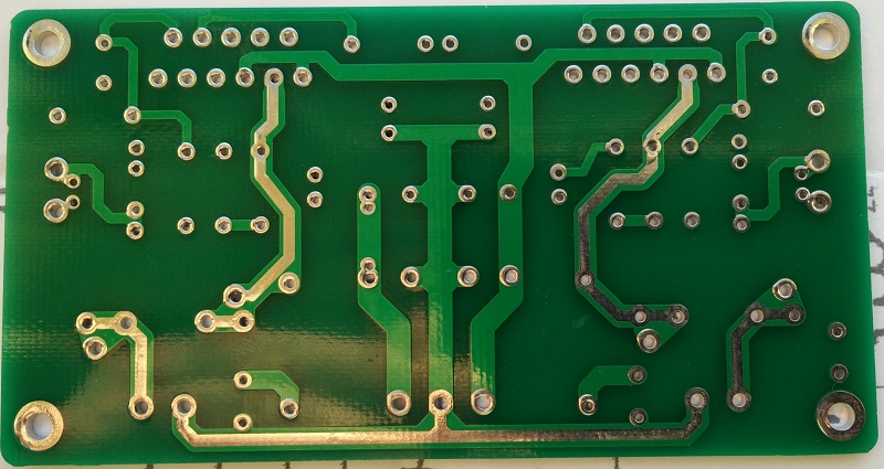
The layout is pretty craptastic, though. The "ground plane" on the top layer is way too fragmented to do anything. It also only connects to the ground connector, so it's utterly useless as a ground plane.
The supply routes are skinny traces, rather than pours, leading to higher supply inductance. The feedback ground and input ground are routed separately ... to the power connector. You actually want them terminating at the output connector. It's interesting with the apertures in the solder mask on the output traces. That's an old trick to get a bit lower resistance of the traces. However, it only works if the board is wave soldered. The idea is that the solder will stick to the exposed parts of the traces as the board travels through the solder bath and lower the trace resistance.
Basically, the designer missed just about every opportunity to use the available copper to improve performance. They ended up with a connect-the-dots layout, just as most other people. They did dress it up a bit, but, sadly, not in a way that will do anything for performance.
I guess the good news is that the performance you'll get with this board is about the same as with most other LM3886 boards out there. I have yet to find anyone who have taken the LM3886 layout to the level I use in the Modulus-86. Of course, in the Modulus-86, I take the performance to a whole new level by adding another feedback loop and about 140 dB of loop gain to drive the THD down into the abyss.
You'll probably get quite a bit out of my Taming the LM3886 page as linked to by Mike above. I also suggest taking a look at my measurements of the THD of various layouts in this thread: http://www.diyaudio.com/forums/chip-amps/252436-lm3886-pcb-vs-point-point-data-3.html#post3846783
~Tom
First off, add 22 kOhm in series with 47 pF across the 22 kOhm feedback resistor. This is to prevent excessive overshoot on the transient response caused by the noise gain compensation (220 pF cap across the amp inputs). Adding these components also reduce the peaking in the frequency response around 100 kHz where the noise gain compensation kicks in.
As Daniel writes, I suggest increasing the 22 uF capacitor to 220-1000 uF for lower THD at 20 Hz.
Also increase the two 220 uF supply decoupling capacitors to at least 1000 uF (National Semiconductor/TI recommends 470 uF per LM3886 in the data sheet).
Further, I suggest decreasing the 10 ohm resistor in the Thiele Network to 1.5 ohm to better dampen the ringing under capacitive load. Oh, and the eBay seller probably didn't bother to tell you how to wind the inductor... 15 turns of 18 AWG (1 mm diameter) enameled magnet wire on a AA battery will form an inductor of about 2 uH. Perfect for a Thiele Network.
I do not agree with Daniel's recommendation to increase the feedback resistor to 27 kOhm. First off, you don't need the extra gain. The amp as-is will clip around 1.65 V RMS and most hifi sources these days provide 2 V RMS. The MiniDSP is the only source I know of that strays from this standard with a 0.9 V RMS output voltage. Secondly, you get worse performance at higher gain due to the resulting reduction in loop gain.
The layout is pretty craptastic, though. The "ground plane" on the top layer is way too fragmented to do anything. It also only connects to the ground connector, so it's utterly useless as a ground plane.
The supply routes are skinny traces, rather than pours, leading to higher supply inductance. The feedback ground and input ground are routed separately ... to the power connector. You actually want them terminating at the output connector. It's interesting with the apertures in the solder mask on the output traces. That's an old trick to get a bit lower resistance of the traces. However, it only works if the board is wave soldered. The idea is that the solder will stick to the exposed parts of the traces as the board travels through the solder bath and lower the trace resistance.
Basically, the designer missed just about every opportunity to use the available copper to improve performance. They ended up with a connect-the-dots layout, just as most other people. They did dress it up a bit, but, sadly, not in a way that will do anything for performance.
I guess the good news is that the performance you'll get with this board is about the same as with most other LM3886 boards out there. I have yet to find anyone who have taken the LM3886 layout to the level I use in the Modulus-86. Of course, in the Modulus-86, I take the performance to a whole new level by adding another feedback loop and about 140 dB of loop gain to drive the THD down into the abyss.
You'll probably get quite a bit out of my Taming the LM3886 page as linked to by Mike above. I also suggest taking a look at my measurements of the THD of various layouts in this thread: http://www.diyaudio.com/forums/chip-amps/252436-lm3886-pcb-vs-point-point-data-3.html#post3846783
~Tom
Last edited:
Sounds like a bit of a lemon. Never mind. So there aren't any 'basic' (just the LM3886 + datasheet components) PCBs, that are readily available on Ebay, that stand out as well engineered?John
I'm not seeing that you got a poorly engineered lemon. There seems to be at least some agreement that the circuit you have is approximately what the factory recommends, so how bad is it going to be?
I don't dispute statements made by those who have worked their personal magic on the LM3886 and other chips, but I do think it's fair to mention the engineering staff at Texas International. As far as I know TI doesn't hire from the bottom 10% of the class, and degreed engineers do tend to hold master's degrees. These are the people who created both the chip and the circuit it works in, so how wrong are they going to be?
I think it's also fair to look at the broader spectrum. In this age of little black chips amplifiers tend to have dead-straight response curves. But now look at the response curve for any given speaker. Even if your speakers cost in the $3,000 range--apiece--is .001% going to do you any good? That's one-one-thousandth of one percent.
Again, I don't argue with anybody's ideas or assertions, but the gist of the comments I've read seems to be, "That's just the factory circuit." So I guess it's in the eye of the beholder whether the guys at the factory know what they're doing. But after all, they did build the chip.
.
Last edited:
I'm not seeing that you got a poorly engineered lemon. There seems to be at least some agreement that the circuit you have is approximately what the factory recommends, so how bad is it going to be?
The board is not terrible. It's about average for an eBay board. The designers do get plus points for including Cc (across the inputs of the amp) and the Thiele and Zobel networks. Sadly, they didn't follow the recommendations for decoupling and forgot to compensate the overall frequency response for the addition of Cc. And they didn't do anything special to the layout. They connected the dots... This is what most people do.
Use the boards and get average performance. Nothing wrong with that. If you want world class performance, I suggest looking at my Modulus-86.
I don't dispute statements made by those who have worked their personal magic on the LM3886 and other chips, but I do think it's fair to mention the engineering staff at Texas International. As far as I know TI doesn't hire from the bottom 10% of the class, and degreed engineers do tend to hold master's degrees. These are the people who created both the chip and the circuit it works in, so how wrong are they going to be?
TI = Texas Instruments. The LM3886 was made by National Semiconductor. TI acquired National in 2011. National tended to hire good people as well.
Speaking of... Bentsnake, you may be interested in reading my resume. It's available on my website, www.neurochrome.com. It's been over a year since I last updated it, but I think you'll find it informative...
")
I think it's also fair to look at the broader spectrum. In this age of little black chips amplifiers tend to have dead-straight response curves.
Sure. In an optimized layout using a laboratory power supply, the ICs have good performance. This is the performance you see in the data sheet. However, with a poor layout and an unregulated supply, the ICs don't perform as well.
Below is shown the impact on the performance of the LM3886 versus various layouts. I described the experiment in detail in Post #30 of the LM3886 P2P vs PCB (with data) thread. The differences in performance is caused by moving the ground connections around. There were no schematic changes - only layout changes.
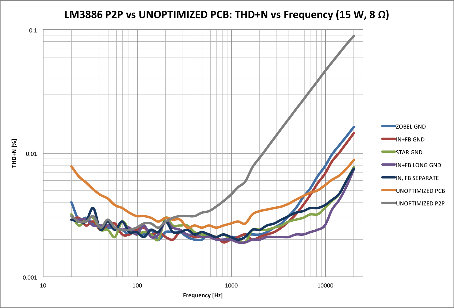
The image below shows the THD+N of the LM3886 in an optimized layout using a regulated lab supply (Agilent E3632A) and using a regular unregulated supply (toroid + bridge rectifier + 2x22000 µF). The data was captured using an Audio Precision SYS-2712. Click on the image for a larger view.

~Tom
Last edited:
Since I have all the bits, I'll make this one up with a few changes to component values, and stick it in a box.
I'm a bit stuck for the caps. The board 'designer' has put the footprint (0.2" pitch) for the two power supply bypass caps just a fraction too close together for two 12.5mm diameter caps to sit flush to the board - they have to **** outwards. 10mm works fine. If I'm prepared to tolerate wonky caps, the maximum value I can find is 1000uF/50V, or if I must have straight caps, 470uF/50V. Grrr.
The 22uF cap has, inexplicably, a lead pitch of 3mm. My normal UK supplier (CPC) has no capacitors with that lead pitch. Farnell/Element 14 (the same group as CPC); none. RS have a few, but then I'm into MOQ problems. At least the voltage rating shouldn't be a problem - if I'm reading it right, that cap only ever sees the maximum input voltage swing? So a 10V cap should be fine?
Cheers
John
. . . First off, add 22 kOhm in series with 47 pF across the 22 kOhm feedback resistor. This is to prevent excessive overshoot on the transient response caused by the noise gain compensation (220 pF cap across the amp inputs). . . . I do not agree with Daniel's recommendation to increase the feedback resistor to 27 kOhm. First off, you don't need the extra gain.
Depending on the drive (in)capability of the source, such as anything modern, like a computer device, some more power amp gain may be useful so that the source doesn't distort itself very badly well before the amp potential is reached.
That sort of thing is typical today.
So I think we ought to give the amp owner the choice.
But I do have a question:
How does the amp compensation parts (with that 47pf) need to be changed if when the feedback resistor is 27k?
It's about average for an eBay board...Use the boards and get average performance...If you want world class performance...
If I want wold class performance I'll look to a world class manufacturer doing business worldwide, and offering a world class warranty. Not to some advertising puffery claiming to remove unwanted facial hair and cook chicken 50% faster.
Even less so when the claims are made by some guy so desperate for advertising copy that he quotes my unrelated comments out of context. This effort to twist my words to promote your product is legally questionable, and ethically seriously over the line.
Looking at what I think can be called facts, the LM3886 was developed at National (acquired by Texas International in 2011) by a team of at least one senior, and several junior, experienced audio engineers. The procedure was to test, retest, and test again in a lab equipped with hundreds of thousands of dollars worth of equipment.
After which millions of dollars were spent to build a factory equipped with automatic production machines. Such expense is necessary because these chips are too small and complex to be built by hand, automatic self-correcting machinery is required. Production runs in such a factory are in the millions, serving a worldwide market. Each of those millions of chips backed up by that world class warranty.
Enter now the used car salesman, who announces yeah all of that is fine but I'm smarter than all those guys, which is how I did better than them working in a corner of my rumpus room. And look here, this sworn statement that I wrote and signed proves it. Oh and by the way my brother in law is an investment counselor, here's his card.
But no, your assurance that grandma drove it only on Sundays is meaningless to me. So are your claims to superior engineering insight, and likewise a lot of claims you make about your tests run on your equipment under your conditions in your rumpus room. I'm forced to consider the term "independent testing laboratory."
Don't misunderstand, I don't mean to disparage your product in any way. I'm sure the anti-aging formula you discovered in the monasteries of Tibet works fine. Neither do I say that you shouldn't advertise your product. To the contrary I say go for it, and if your advertising methods include knocking the other guy's product, well that's your decision..
But please be so good as to leave me out of it. I know or care nothing about you or your product, so please don't twist the meaning my words in your attempts at self-promotion. Leave me in peace as a disinterested--totally disinterested--third party, and while you're at it tell your brother in law to get a real job.
.
Last edited:
Looking at what I think can be called facts, the LM3886 was developed at National (acquired by Texas International in 2011) by a team of at least one senior, and several junior, experienced audio engineers. The procedure was to test, retest, and test again in a lab equipped with hundreds of thousands of dollars worth of equipment.
After which millions of dollars were spent to build a factory equipped with automatic production machines. Such expense is necessary because these chips are too small and complex to be built by hand, automatic self-correcting machinery is required. Production runs in such a factory are in the millions, serving a worldwide market. Each of those millions of chips backed up by that world class warranty.
Enter now the used car salesman,
.
Snipping out your somewhat uncalled for personal attack on Tom. You are missing something important. There is the chip, there is the reference circuit. And there is the implementation, including PCB layout. You can gain a huge improvement by getting the layout right and you can make it a lot worse by getting it wrong. Nothing to do with the quality of the engineers who designed the LM3886.
Tom oddly is an IC designer, even more oddly with TI. I don't know but he might even know the designers of the 3886 in a professional basis. What I do know is he knows more about IC production than you or I do. He also has the test equipment to actually demonstrate things.
If you look at Toms website and his posts on other threads he shares his knowledge a lot. He does sell an example of what you can do with the 3886 if you push it to the limit, but this does not in anyway affect the advice he gives other builders of 3886 based amps. Something he said has clearly touched a nerve with you, which is a shame as no need to get upset by it.
As billshurv has pointed to, I am an IC designer with 10+ years of industry experience. I worked for National Semiconductor and now work for TI. I worked for two years in the Precision Amplifiers group under National Semiconductor and was the lead designer on the LMP2021 precision op-amp. I believe it is still providing the lowest noise floor in the industry for auto-zero op-amps. Also its -400 nV (yes, nanovolt) of systematic offset (TYP) speaks volumes to the precision involved.
In 2007, I was reorged into the Precision Timing group where I design precision high-speed circuits. Among other things, I design the precision DC bias blocks used in our PLL/VCO products, crystal oscillators with industry-leading phase noise performance, etc. The work I do in my day job is about as hard core analog as you can get...
As a co-inventor, I hold one US patent (#8446193).
I am very intimately familiar with the CMOS, BiCMOS, and SOI BiCMOS processes used in modern semiconductor manufacturing. I am intimately familiar with the circuit design involved in mass produced circuits. That's what I do every day... I work closely with the test engineers who test the ICs in manufacturing and am quite familiar with the capabilities of the testers. The product characterization lab I have access to at work contains millions of dollars worth of equipment. That's the lab in a smallish remote design center. The labs in Dallas and Santa Clara contain even more equipment.
That's not counting my lab at home, which I use for my Neurochrome product development. The Audio Precision APx525 I use for my testing was $12500. That's just one piece in my lab.
I know exactly what it takes to bring a product to market. I know the level of testing, characterization, and detail that goes into producing the data sheet figures and tables. I know this stuff because I have done it. Multiple times. I also know what the characterization and test boards look like, because I consult on the layout of them and use them in my product testing.
Prior to my industry experience, I completed my Master's Degree in Electrical Engineering in 2002 from the University of Washington. I was three years into my PhD studies when I was offered an internship with National and decided to jump ship.
All this information is available for anyone to see on my resume and Linked-In profile. Of course, getting to it requires effort... Like clicking a link on a web page. I provided the link in my earlier post... Here it is again: Tom Christiansen, Neurochrome :: Audio (Boy, I really need to update that resume).
Bentsnake, it is unfortunate that you choose to consider me a "used car salesman" because I strive for high performance. Yes, I have a product to sell and I am proud of it. However, I base my claims in science and engineering. I back up my claims with data.
In addition, I strive to move the DIY community forward by allowing DIYers to easily obtain the background information needed to make good design decisions. My Taming the LM3886 Chip Amplifier page is an example of this. Of course, earlier you found it necessary to completely discredit this effort because reading a website is just too much work. That's pretty sad...
I am keenly aware of the impact of the circuit layout. I know this both from my day job and from my measurements of the LM3886 in various layouts. I also know from my latest tweak to the Modulus-86 amplifier. From Rev. 1.0 to Rev. 2.0, I improved the residual mains hum from -110 dBV to below the -135 dBV noise floor with a small layout tweak. I have backed up my claims with data. Feel free to reproduce my measurements of the LM3886. All that is required to do so is a good sound card and a little software... Oh, and some effort...
~Tom
Last edited:
With most amplifiers, the parameters of good stability/tone versus good imaging are in conflict. Generally we have to balance the tone versus imaging compromise to suit. With a simple amp, when you get more of one aspect, you'll get less of the other.
A nested/composite approach of enclosing the LM3886 within the feedback loop of a much nicer sounding small signal op-amp, as seen with the Modulous86, is an approach that boosts imaging performance And gives a pleasant tone, simultaneously. That is rare.
See the difference?
A nested/composite approach of enclosing the LM3886 within the feedback loop of a much nicer sounding small signal op-amp, as seen with the Modulous86, is an approach that boosts imaging performance And gives a pleasant tone, simultaneously. That is rare.
See the difference?
With most amplifiers, the parameters of good stability/tone versus good imaging are in conflict. Generally we have to balance the tone versus imaging compromise to suit. With a simple amp, when you get more of one aspect, you'll get less of the other.
I'd be very interested in reading the research that led to this conclusion. Do you have a reference to any peer-reviewed research papers that back this up?
The research I'm aware of, that is accessible outside of a paywall, is that done by Sean Olive at Harman Kardon. He publishes his findings in AES papers (inside paywall) with good summaries, including data in his blog, Audio Musings by Sean Olive.
From what I understand, you need a flat frequency response, low THD, low IMD, and linear power response across the entire audio range. Few amplifiers deliver this. Those that do, sound good and natural. Other amplifiers may color the sound in a certain way that some find pleasing or color the sound in unpleasant ways. The research shown by Olive indicates that to sound good to the majority of listeners, an audio system has to measure well. Of course, this is only one data point, but sadly that's all that is available outside a paywall. If you know of other research on the topic, I'm most interested.
A nested/composite approach of enclosing the LM3886 within the feedback loop of a much nicer sounding small signal op-amp, as seen with the Modulous86, is an approach that boosts imaging performance And gives a pleasant tone, simultaneously. That is rare.
A composite amp uses loop gain to maximize performance across all parameters. I agree with your assessment that reaching production quality with a composite topology is indeed rare. But then again, I'm biased...
May I interest you in a fine pre-owned automobile? 
~Tom
Last edited:
Tom,
Kudos to you for the restraint shown in this thread. In the same circumstances, I would not be so pleasant.
Thanks. I appreciate it.
~Tom
Sure, but it is a perception means. Acutance - Wikipedia, the free encyclopedia That specific form of ringing, is for audio what a photoshop sharpening filter is for photos. Most of the low-parts-count amp kits do this, resulting in fantastic imaging at the cost of impractical tone. Much of the tone problem and a little audio can be swamped by biggie size decouplers, like 47 labs and Audiosector use. Mainly, just one chip has the problem of all of your eggs in one basket.I'd be very interested in reading the research that led to this conclusion. Do you have a reference to any peer-reviewed research papers that back this up?
P.S.
Personally, I would rather use a composite amp instead--so much less compromise--so much better sound.
Oh, I think I understand what you mean. It's the same effect that cause some people to prefer the sharp/harsh (in my experience) rendering of a thin metal cone speaker. To them it sounds precise. To me it sounds harsh. It's all related to cone break-up, which can be picked out pretty easily in the directivity (SPL vs listening angle), THD, and impedance curves of the speakers.
~Tom
~Tom
- Status
- This old topic is closed. If you want to reopen this topic, contact a moderator using the "Report Post" button.
- Home
- Amplifiers
- Chip Amps
- An Ebay LM3886 PCB - comments invited