"I'm not cheating and sticking in a small solid-state preamp like others have done in the past. I am operating the tube in a manner that is fundamentally different from all other methods employed over the past century, utilizing a novel drive and using enabling new technologies that have come out in the past few years."
Finally, something new since the tubes were invented. Patent pending no doubt...
2A3 is biased at -55V, with 0.5V input to reach full power, the gain required is 110x, where does it come from?
Finally, something new since the tubes were invented. Patent pending no doubt...
2A3 is biased at -55V, with 0.5V input to reach full power, the gain required is 110x, where does it come from?
Last edited:
Listening to Johnny Cash's cover of Hurt, you can feel an anguish in his voice that simply isn't there with other amps.
Riiiiiight.
Kind of reminds me of a saying my pop was fond of "if it sounds too good to be true, it probably is".
Step-up transformer, secondaries grid to cathode, cathode resistor bypassed to B+, low impedance source (headphone amp).
Sheldon
Sheldon
Not only you. He's cheating as well, running the 2A3 at 20W anode dissipation..I have just found one interesting project on the web that is maybe relevant to this project, it uses one 2A3 per channel and at 5WATT output claiming 0,211% distortion without any feedback used and without any gain stage - I find it hard to believe!
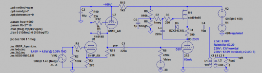
I attached a probably more reasonable concept using a mosfet active load. Yields similar distortion figures, Zout is really low, high damping factor, and you can use PP opts or even cheapie toroidals. No dc coupling though...
Edit: output power is ~4.8W pure class A1.
Attachments
Last edited:
Just one more detail from the description, input impedance is only 600 Ohm's > which means he is using step-up transformer to amplify signal.
Step-up transformer, secondaries grid to cathode, cathode resistor bypassed to B+, low impedance source (headphone amp).
Could also choke load the tubes and have small OPT and parafeed cap inside case.
deafbykhorns,
Have you got round to doing a sim of the GM70 circuit with cap coupled pentode driver?
Have you got round to doing a sim of the GM70 circuit with cap coupled pentode driver?
Been busy building a home automation system (HAI) at the house....
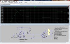
Take a look at this, just did a quickie, bandwidth looks much better.
Looks like it slightly goes into A2, getting about 24watts or so.
I'm in the process of gathering parts for a breadboard build, might take me a couple months but I'll post some updates.
Take a look at this, just did a quickie, bandwidth looks much better.
Looks like it slightly goes into A2, getting about 24watts or so.
I'm in the process of gathering parts for a breadboard build, might take me a couple months but I'll post some updates.
Attachments
Last edited:
Hi Goldenbeer.
I have now built the darius loftin-white using 6sl7 and 2a3. This is a superb little amplifier. Thanks to Sheldon for useful advice.
Some of my resistor values are different than yours since I did my own calculations. I also don't use R6...
Running 420V on the plate, 178V on the cathode (BIG 3.5K Ohm cathode resistors), 130v on the grid (-40v bias) into el-cheapo 3.5k Tomiko single ended OPT's...
For the cathode follower I am running about 1.75mA - Mu is most linear at this current according to the specs sheets. For the differential amplifier I am using 1.2k ohm on the cathode, and 2x140k Ohms on the anode.
Bass is superb. Tight fast little amplifier. Gives me goosbumps already... Definitely worthy of better Iron.
Ian
Last edited:
Member
Joined 2009
Paid Member
Just one more detail from the description, input impedance is only 600 Ohm's > which means he is using step-up transformer to amplify signal.
+1
Which just shifts the burden to the pre-amp. In essence, it still needs a driver. And the frequency response is similarly constrained.
I have now built the darius loftin-white using 6sl7 and 2a3. This is a superb little amplifier. Thanks to Sheldon for useful advice.
Some of my resistor values are different than yours since I did my own calculations. I also don't use R6...
Running 420V on the plate,...
🙂 You're faster than me building this amp - pleased to hear it works for you. My variation still exists on paper only...
If you leave off R6, you are probably running the 6SL7 beyond specs, which may be a problem - or not. Anyways, glad to hear there's no arcing over during start up. What voltage potential are you running the 6Sl7 heater at? Also, are you using a SS or tube rectifier?
That's what I would expect.Bass is superb. Tight fast little amplifier. Gives me goosbumps already... Definitely worthy of better Iron.
(using the right speakers..)
GB
The 6SL7 is still in spec. I am running the heaters elevated at about 65 Volts. It might be well to consider a separate heater supply for the follower though, since as the 2a3 ages, it will draw less current and the HT+ will rise.
This is all currently on a bread-board and might look different if it were more permanent, say in a chassis. 🙂
Right now I turn on the 2a3 heaters with one switch (they are on a separate transformer), wait a couple of minutes then turn on the HT+ mains transformer. I will likely use a 2 min time-delay relay for this in the future.
The HT+ is rectified using two 6AU4-GT's in a graetz bridge. I can highly recommend this type of rectification. It's the best of both worlds. If your power supply is not able to handle the current draw of the 6AU4 then 6AX4 or similar is possible. Avoid the standard fare 5 Volt Hi-Fi rectifiers...
Interresting little experiment: if I hook up a 2a3 to an output transformer and a full-range speaker, and just run the heaters using AC (no HT+) there is hum. Even without HT+ there is hum. However if I disconnect the cathode resistor so the heaters are floating the hum immediately dissapears. Please note that when the cathode resisitor is attached it is placed in a well balanced position (most use a hum-bucker or similar arrangement to do this). This small hum can ONLY be from the heater AC...
Such a hum is inevitable with AC heating (even 2a3). BUT: If you by-pass the cathode with a capacitor then the hum immediately dissapears. Of course that completely defeats the purpose of the Loftin-white! So we won't be doing that. 😉
What this means you have to also create a little circuit to cancel the heater noise. Just working on it now...
Darius-Karim Mottaghian-Milani did it for his 300b amplifier here:
Loftin White: Direkte Heizung 300B
Ian
🙂 You're faster than me building this amp - pleased to hear it works for you. My variation still exists on paper only...
If you leave off R6, you are probably running the 6SL7 beyond specs, which may be a problem - or not. Anyways, glad to hear there's no arcing over during start up. What voltage potential are you running the 6Sl7 heater at? Also, are you using a SS or tube rectifier?
That's what I would expect.
(using the right speakers..)
GB
Last edited:
BTW - if you use DC heaters then you shouldn't have any hum. Somewhere around here I have a nice little DC heater circuit for 6B4G....
Member
Joined 2009
Paid Member
Interresting little experiment: if I hook up a 2a3 to an output transformer and a full-range speaker, and just run the heaters using AC (no HT+) there is hum. Even without HT+ there is hum. However if I disconnect the cathode resistor so the heaters are floating the hum immediately dissapears. Please note that when the cathode resisitor is attached it is placed in a well balanced position (most use a hum-bucker or similar arrangement to do this). This small hum can ONLY be from the heater AC...
Such a hum is inevitable with AC heating (even 2a3). BUT: If you by-pass the cathode with a capacitor then the hum immediately dissapears. Of course that completely defeats the purpose of the Loftin-white! So we won't be doing that. 😉
Would it be correct to say that the only way you can get hum in the speaker is if there is ac current flow through the OPT secondary. It either gets generated by ac current flow through the primary or it gets picked up magnetically from an adjacent coil. I can't quite picture the circuit for your experiment - it would be good to see where the currrent is flowing.
Would it be correct to say that the only way you can get hum in the speaker is if there is ac current flow through the OPT secondary. It either gets generated by ac current flow through the primary or it gets picked up magnetically from an adjacent coil. I can't quite picture the circuit for your experiment - it would be good to see where the currrent is flowing.
Yes, it would be nice to see electrons flow. 🙂 It might be due to the cheap OPT's or cheap 2a3's I am using. From personal experience, well shielded high quality OPT's don't exhibit this.
But the point is that to build a really rock solid quiet circuit you need to deal with the AC heater noise. Or use DC heaters...
Last edited:
Replaced a noisy cheap OPT with another one now... wow - this little amp is really, really good. Running the 2a3 even a bit cooler now at about 220v A-K and the imaging is impressive. I'm thinking of working up a similar schematic for 45's now.
Hi there,
I am planning to build a 2A3 SET amp, and have been comparing various circuits. Currently, the available choices have burned down to the following three...
1. "Fi Primer" LW SRPP-style
Pros:
- good distortion figures
- apparently tried & tested
- minimum number of total 2 stages only
Cons:
- only very low current across SRPP stage, with tolerances of tubes affecting sonics and maybe sounding wimpy overall in RL(?)
2. Shishido
Pros:
- tried and tested, long time favorite
- better current across paralleled 6SL7
Cons:
- uninspired circuit, average sonic properties??
3. Bootstrapped cathode follower
Pros:
- very low distortion of pre-stages at full power
- lowest output impedance, best drive for 2A3
- no need for bypass cap in pre-stage
Cons:
- additional stage, 3 stages total
- introduces additional cap for bootstrapping
- highest distortion at output at full power
- does not seem very popular, untested in RL(?)
All three topologies deliver about 3W rms into 8R impedance speakers using 2.5K primary trannies.
I have modeled all three circuits in ltspice. I adjusted #2 from the original plan using 12AX7 and 450v B+ to 6SL7 and 400v B+, for comparison purposes and because that's what I am going to use (at least the B+).
The cathode follower circuit has been sketched up by myself, using details from various sources, but there seems to be no tried and working instance around anywhere, so watch out. There may be kinks or room for further improvement.
Now, my question to you guys.
Anyone who tried these configs can comment on them from RL experience? Is there any mess up or striking error in the 3rd circuit?
Thanks & greetz to all
IMHO the Shishido is a good direct coupled amp. Sounds good and is very easy to build.
But it still is a SE amp. This means irons are the critical issue.
My suggestion is to choose the BEST power supply transformer and filter choke you can afford.
You would be surprised to listen to the difference between an average quality power transformer and a top quality one.
A good OT will also help, of course 😉
- Status
- Not open for further replies.
- Home
- Amplifiers
- Tubes / Valves
- 3 direct coupled 2A3 amps