.
I do like the chunk of wood idea. But to me at least, your circuit would be readable if you'd number the TDA1519 pins. Else how is it possible to discuss the circuit?
It's also customary to number components, and to refer to them by number. After all, there might be a dozen 0.1uF capacitors.
But all that aside, I'm still befuddled. What did you say was wrong with this circuit?
.
Attachments
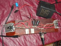
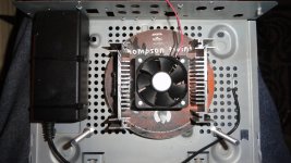
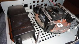
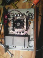
OK, here it is so far. It would seem I'm trying for some "Most ugly amp" award.
I think most certainly I will need more than 4400uF of capacitance after the bridge. 3.3A worth of PS. I noted my 100uF is too small at 16V...I will need to scrounge around for a matching 100uF@50V. The 1.0uF PS cap is at the pins of the chip & the 2200uF caps are centrally located.
I do have an old VCR enclosure sheetmetal shell & some particle board to "clean it up". Perhaps I can dig up a DPST switch somewhere & tie it to the "Standby switch", rather than simply plugging it into the PS.
PS, that lump of wood is Quebracho Colorado & weighs some 5lbs easily.
I have my concurrent Infinity Qb rebuild at the same time...
____________________________________________________Rick.........
Attachments
what 100 uF cap?
The cap as illustrated off pin 3, Supply voltage ripple rejection.
__________________________________________________Rick.........
.
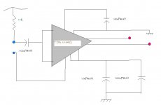
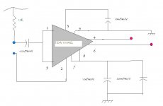
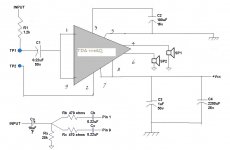
I guess you redrew the factory schematic just for clarity to yourself? Good idea. I reworked yours for clarity to me.
a. The reason for R1 is unknown to me.
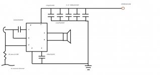
b. The whole input circuit is a bit mysterious, at least to me. Are you splitting a mono audio signal to send it through both channels of the TDA1519?
If so, I'm not sure pins 1 and 9 can be shorted together successfully. If you're going to split/mix mono/stereo, then something like the shown Y network might work. It's a turned-around shameless rip of Figure 1 on this page by Rane: Why Not Wye?
Ca might or might not be needed, depending on what the input device might be.
c. The factory mandates a 1,000uF capacitor following SP1 and SP2. I suspect that without this capacitor the circuit will smoke, because this is a DC blocking capacitor.
d. There's no indication of what you have in mind for TP1. The factory specifies that this conductor shall run separate from all others to the power supply ground point. The "ground" side of the 1,000uF capacitor should also be run separately. This is done to keep the audio signal from being distorted by the comparatively huge power supply voltages and currents.
<< I think most certainly I will need more than 4400uF of capacitance after the bridge. >>
I'd think a 4400uF capacitor bank would be fine, but more certainly won't hurt.
<< 3.3A worth of PS. >>
3.3 amps at, say, 12 volts is 40 watts. This might be overdoing. Use the rule of thumb that watts = volts x amps = VA
Two channels running at 6 watts each is 12 watts. Transpose:
watts = volts x amps
amps = watts / volts
amps = 12 watts / 12 volts = 1 amp
Power supplies should/must be oversize by about 1.5 or 2, so this translates into a transformer rated around 12VAC 2VA. Remember that you lose 1.4 volts across the bridge rectifier, but this probably is not significant.
All of that said, there's nothing wrong with the 3.3 amps you specified in the first place. Only that transformers are the expensive part of an audio amp, everything else is spare change (except an enclosure). Here's a page just for reference. http://www.jameco.com/Jameco/catalogs/c151/P100.pdf
Additionally:
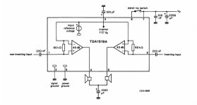
Note that pin 5 of the TDA1519 is specified as "substrate," which I take to mean the metal mounting tab. If this is correct, then the heat sink will be part of the TDA1519 circuit. If so, DO NOT let the metal heat sink contact any other conductive parts, or else use an insulated mounting kit for the TDA1519. All of which might be wrong, I don't know, but that's my best advice.
All the different capacitor voltage ratings seem unnecessary. I personally use electrolytic caps rated at 50 volts, 105 degrees.
I've personally had excellent results with parts from Thai Shine on eBay, very fast USA shipper. Here's a link, or they'll come up in a vendor search: 1 4W 5, Ceramic Disc Capacitors items in Thai Shine store on eBay!
DISCLOSURE: Neither Rane, Jameco, nor Thai Shine send me money. I wish they'd do something about that.
.
I guess you redrew the factory schematic just for clarity to yourself? Good idea. I reworked yours for clarity to me.
a. The reason for R1 is unknown to me.
b. The whole input circuit is a bit mysterious, at least to me. Are you splitting a mono audio signal to send it through both channels of the TDA1519?
If so, I'm not sure pins 1 and 9 can be shorted together successfully. If you're going to split/mix mono/stereo, then something like the shown Y network might work. It's a turned-around shameless rip of Figure 1 on this page by Rane: Why Not Wye?
Ca might or might not be needed, depending on what the input device might be.
c. The factory mandates a 1,000uF capacitor following SP1 and SP2. I suspect that without this capacitor the circuit will smoke, because this is a DC blocking capacitor.
d. There's no indication of what you have in mind for TP1. The factory specifies that this conductor shall run separate from all others to the power supply ground point. The "ground" side of the 1,000uF capacitor should also be run separately. This is done to keep the audio signal from being distorted by the comparatively huge power supply voltages and currents.
<< I think most certainly I will need more than 4400uF of capacitance after the bridge. >>
I'd think a 4400uF capacitor bank would be fine, but more certainly won't hurt.
<< 3.3A worth of PS. >>
3.3 amps at, say, 12 volts is 40 watts. This might be overdoing. Use the rule of thumb that watts = volts x amps = VA
Two channels running at 6 watts each is 12 watts. Transpose:
watts = volts x amps
amps = watts / volts
amps = 12 watts / 12 volts = 1 amp
Power supplies should/must be oversize by about 1.5 or 2, so this translates into a transformer rated around 12VAC 2VA. Remember that you lose 1.4 volts across the bridge rectifier, but this probably is not significant.
All of that said, there's nothing wrong with the 3.3 amps you specified in the first place. Only that transformers are the expensive part of an audio amp, everything else is spare change (except an enclosure). Here's a page just for reference. http://www.jameco.com/Jameco/catalogs/c151/P100.pdf
Additionally:
Note that pin 5 of the TDA1519 is specified as "substrate," which I take to mean the metal mounting tab. If this is correct, then the heat sink will be part of the TDA1519 circuit. If so, DO NOT let the metal heat sink contact any other conductive parts, or else use an insulated mounting kit for the TDA1519. All of which might be wrong, I don't know, but that's my best advice.
All the different capacitor voltage ratings seem unnecessary. I personally use electrolytic caps rated at 50 volts, 105 degrees.
I've personally had excellent results with parts from Thai Shine on eBay, very fast USA shipper. Here's a link, or they'll come up in a vendor search: 1 4W 5, Ceramic Disc Capacitors items in Thai Shine store on eBay!
DISCLOSURE: Neither Rane, Jameco, nor Thai Shine send me money. I wish they'd do something about that.
.
Attachments

Last edited:
<< I noted my 100uF is too small at 16V >>
Actually no, if your power supply is 12 volts, then a 16 volt capacitor will be fine.
PS: It's just my opinion, but it seems to me that paragraphs aid comprehension.
.
Actually no, if your power supply is 12 volts, then a 16 volt capacitor will be fine.
PS: It's just my opinion, but it seems to me that paragraphs aid comprehension.
.
<< there's no terminal for B+ >>
Integrated circuits (ICs) don't have B+, that's tubes/valves. ICs have Vcc positive, and Vee negative, power supply voltages.
.
Integrated circuits (ICs) don't have B+, that's tubes/valves. ICs have Vcc positive, and Vee negative, power supply voltages.
.
Last edited:
That's right, Vcc, or a +Vcc & a -Vcc, it's been awhile. I'm doing up a 12B4 Single-ended amp, paused for now till I get a hold of Bazziamps.com.ar to see if they still have my transformers I designed it for...
Also I have my Infinity Qb rebuilds coming together. Then this literally dropped on my lap. I took in my brother-in-laws big ol' Sony CRT TV that conked out.
As we have TVs in every single room, if wanted, I pulled the Sony apart...looking for the amp section. I have a 2822 based amp running my audio thru the computer "in the back", but I want more than a sub one watt power to make my PC music. I'm contemplating another 2-Way loudspeaker build, this would be eating up all of my 600mW of power. I have all the drivers ready to go, the Enclosure volume & arrangement ready. Just need to do the woodworking.
So I find these two TDA1519AQ each running bridged, for a 22W max each channel, but with an atrocious 10% distortion at that high a power. Halving the power gets into the sub 1% values.
That is may what is confusing you...they are bridged...note the PIX & you'll see TWO of these chips riding outboard of the piece of wood.
_______________________________________________Rick.........
.
Pics? People look at pics? No way I could handle that, I can barely deal with schematics.
From what you say...hmmm...have you considered a nice LM1875? Costs $2-3 each, genuinely hi-fi, and highly regarded among chip amp folk. Plug the TV's headphone output into the amp and you're rolling. Just a thought.
http://www.ti.com/lit/gpn/lm1875
.
Last edited:
<<Two channels running at 6 watts each is 12 watts.>>
<<Power supplies should/must be oversize by about 1.5 or 2, so this translates into a transformer rated around 12VAC 2VA. Remember that you lose 1.4 volts across the bridge rectifier, but this probably is not significant.>>
make that least 12 VA rated instead of 2 VA.
but better off with something over 20VA rated.
<<Two channels running at 6 watts each is 12 watts.>>
<<Power supplies should/must be oversize by about 1.5 or 2, so this translates into a transformer rated around 12VAC 2VA. Remember that you lose 1.4 volts across the bridge rectifier, but this probably is not significant.>>
make that least 12 VA rated instead of 2 VA.
but better off with something over 20VA rated.
Awrk. Right. Never mind the calculations that are painstakingly crafted to illustrate how not to do it. 12 watt amp needs 20ishVA transformer. My oops.
(For clarity, actually still the resulting 1 amp, but at 12 volts, which once again = 12 watts. The same 12 watts that you started out with, which still needs a 20ishVA transformer.)
.
Last edited:
update
Ok, it's been awhile & had some time to work on this one.
Some tips as I've been going...do not use a bent drillbit at all, do not handhold the CD when drilling, set it on a perfectly flat surface, lest you crack your "board". It really is delicate & likes to crack, be gentle.
The aluminum coating as far as I can tell, is on the back side of the artwork...I used a hand-drill my wife has for Nail-work...like a jewelers drillbit, so very tiny! For the metal coating I just used a 6mm bit & made a wide bevel on the existing tiny hole, at the top "decal".....to prevent possible shorts. If you zoom in you might see it.
---------------------------------------------------Rick...........
Attachments
- Status
- Not open for further replies.
- Home
- Amplifiers
- Chip Amps
- TDA 1519AQ