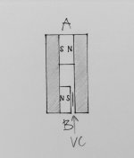
I am building a driver with a linear voice coil (VC) and it works but I would like to optimize the magnetic motor design to increase efficiency and reduce distortions. Here is a sketch of a design (there is a mirror assembly for the return VC):
A and B are Neodymium magnets. Either one could be replaced by steel (1018). Is there any benefit of having both magnets? Magnet B will be close to the VC and maybe needs to be a more temperature resistant version (SH).
Any other suggestion?
A and B are Neodymium magnets. Either one could be replaced by steel (1018). Is there any benefit of having both magnets? Magnet B will be close to the VC and maybe needs to be a more temperature resistant version (SH).
Any other suggestion?
Attachments
Two things about having the Neo that close to the VC:
Non-linearity of the flux in the gap; make a FEMM simulation and find out.
Heat dissipation making the Neo non-magnetic; most Neo can only withstand 80 degrees Celsius.
Non-linearity of the flux in the gap; make a FEMM simulation and find out.
Heat dissipation making the Neo non-magnetic; most Neo can only withstand 80 degrees Celsius.
What is the purpose of this design linear voice coil means nothing as far as I am aware as there is no such thing as a curved voice coil. Depending on what you are trying to achieve will change my answer. Also the only way to truly know is to do a FEMM model. fairly simple to do. I would recommend a different app to design it and then Femm to model it. I would be happy to assist were I can but I am no expert by any means.
Two things about having the Neo that close to the VC:
Non-linearity of the flux in the gap; make a FEMM simulation and find out.
Heat dissipation making the Neo non-magnetic; most Neo can only withstand 80 degrees Celsius.
There are grades like N42SH or N45SH which are surviving 150ºC but they cost more and are mostly special order items.
The only practical improvement to having the magnets split up as shown is a reduction in profile compared to having it in only one spot, which would require more width. The addition of upper section poles (as per your drawing) also gives extra leakage paths and a corresponding reduction in useful gap flux. Running a typical hi-fi speaker with 2 layer coil to the point where the magnets or any part of the pole pieces goes beyond 50 C usually means the voice coil is bound to fail first and soon, and probably isn't the first thing you need to worry about in spite of the popularity of it. If your actual coil volume is Much higher in reality compared the drawing scale, maybe you should think about heat sinking. Simulations are cool if you can guarantee material characteristics, so if you run sims and want to rely on that performance, don't buy your steel from Lowes or Ebay.
Maybe I should describe what I want to achieve is a narrow rectangular voice coil. Sibatech makes something similar http://www.diyaudio.com/forums/full-range/69176-anybody-tried-fal-drivers.html but I want to make it much more narrow, may be no gap between the right and left side of the structure(i.e. one single center steel piece). So this version uses only what I call magnet A but other designs I found use only B like http://harman-kardon.cz/infinity/data/maximum-radiating-surface.pdf (but I would use onle a single voice coil).
One of the reasons to split the magnets is to allow a more narrow shape but I am not sure how much one would gain.
One of the reasons to split the magnets is to allow a more narrow shape but I am not sure how much one would gain.
Last edited:
Well I guess the only real answer is to go download femm And maybe some cad software and play around in it until you are satisfied. Besides the motor what are you trying to make?
I fiddled around with a linear motor recently when I tried to make a planar bass.
I did manage to build them but got stuck on the VC, it was hard to get the accuracy needed.
Some motors, although simulated very well in FEMM, just couldn't be built (well, not to last anyway) and some were in fact lethal.
BTW, FEMM can export DXF if you want the CAD work with it.
I did manage to build them but got stuck on the VC, it was hard to get the accuracy needed.
Some motors, although simulated very well in FEMM, just couldn't be built (well, not to last anyway) and some were in fact lethal.
BTW, FEMM can export DXF if you want the CAD work with it.
I fiddled around with a linear motor recently when I tried to make a planar bass.
I did manage to build them but got stuck on the VC, it was hard to get the accuracy needed.
Some motors, although simulated very well in FEMM, just couldn't be built (well, not to last anyway) and some were in fact lethal.
BTW, FEMM can export DXF if you want the CAD work with it.
Did you mean Import? modeling in Femm I think is pretty clumsy but using a 2d modeler which is easy and then importing to Femm works very well. That is a very good point Solhaga Some things are theoretical but very impractical or even damn near impossible to build.
Nope, I meant export.
You can import as well. But then you'll have to fill in the materials again.
All things considered, I think working in FEMM only is the fastest way.
When you look at the simulation, you'll get a pretty good hunch on what to change.
Like in this example:

Studying the "green fields" lead to:

I could minimize the height in the "sound gap" while maintaining the flux densitiy.
I then exported the shape of the bar only to DXF in order to get a quotation.
You can import as well. But then you'll have to fill in the materials again.
All things considered, I think working in FEMM only is the fastest way.
When you look at the simulation, you'll get a pretty good hunch on what to change.
Like in this example:
Studying the "green fields" lead to:
I could minimize the height in the "sound gap" while maintaining the flux densitiy.
I then exported the shape of the bar only to DXF in order to get a quotation.
QuickField Student version QuickField support site is another possible 2D and axisymmetric option although the node limit may bite you
I am making some bending wave driver so x-max would be less than 1mm. I started with some conventional VC/motors (circular) but when I switched to a rectangular VC I got a more even frequency response and lower distortions. Narrow (1cm) is better than anything wider.Well I guess the only real answer is to go download femm And maybe some cad software and play around in it until you are satisfied. Besides the motor what are you trying to make?
Is there a femm (like) program for Macs?
Ok, I thought you wanted a linear field during a long travel.I am making some bending wave driver so x-max would be less than 1mm.
So this is some kind of Rubanoide?
If it is only one mm then you can have Neos close to each other. Still very hard to build, especially when you can't have any return pole piece?
Probably you won't bother with the heat either as the coil will be very long?
Don't know. Couldn't you run FEMM on some virtual machine on Mac?Is there a femm (like) program for Macs?
Perhaps the Linux version?
I can do some simulations for you just to get you started.
Ok, I thought you wanted a linear field during a long travel.
So this is some kind of Rubanoide?
If it is only one mm then you can have Neos close to each other. Still very hard to build, especially when you can't have any return pole piece?
Probably you won't bother with the heat either as the coil will be very long?
Not an Rubanoide but a flat disk, spider less. VC gap is 1.6-2mm. So the magnetic structure has a return as in my sketch (left half of the cross section).
Any help with a simulation would greatly appreciated.
When I was working on the Rubanoide clone I made some simulations like the one you want, it is easy for me to adjust it to 2 mm or less gap.
How long has the gap to be, that is the height?
How long has the gap to be, that is the height?
2 mm gap (pictures might get squashed in your browser, click on them to get the correct proportions):


An externally hosted image should be here but it was not working when we last tested it.
Thanks! that looks very good.It looks that the thickness of your design is 10mm (steel or magnets). For my design I might have to scale it down to 1/4" (6mm) width to get the width of my voice coil (shape similar to a single VC of http://harman-kardon.cz/infinity/data/maximum-radiating-surface.pdf). I could use a 3/8"or 1/2" common central steel bar for both sides of the magnet structure to save space. The penalty for reducing width would be lower B.n. (hopefully close to 1 Tesla). The height of the gap could stay at 8-10mm.
P.S.: I also played with a Rubanoide design but I have more success with a flat disc bending wave driver.
P.S.: I also played with a Rubanoide design but I have more success with a flat disc bending wave driver.
Magnet width 6 mm, air gap 1,6 mm:

gives almost 1 T!
gives almost 1 T!
An externally hosted image should be here but it was not working when we last tested it.
- Status
- Not open for further replies.
- Home
- Loudspeakers
- Planars & Exotics
- How to optimize Magnet structure?