Hi everyone,
I'm projecting a stereo amplifier using TI's LM4702, I'm using 2 output pairs with BUZ900P/BUZ905P, I'm using MJE15032 and MJE15033 as drivers and BD139 as Vbe multiplier. The amplifier has +/- 50 V supplies, RLmin = 4 ohm, and it's intended for operation with Tamb = 50 °C.
The maximum heatsink temperature allowed is arround 60 °C, and thermal shutdown is at 70 °C.
I'd like to use only one heatsink, but I can use two, one for each channel (right and left).
I'm looking at some heatsinks, like:
Fischer Elektronik SK56-150-SA (0.35 °C/W)
Fischer Elektronik SK56-200-SA (0.3 °C/W)
ABL Components 193AB2500B (0.32 °C/W)
The problem is that I never worked with metals and I don't know how many transistors this heatsinks can have attached. And how to attach them?
There is any heatsink with pre drilled holes for 14 transistors? Where I can get it?
Best regards,
Daniel
Last edited:
Hi everyone,
I'm projecting a stereo amplifier using TI's LM4702, I'm using 2 output pairs with BUZ900P/BUZ905P, I'm using MJE15032 and MJE15033 as drivers and BD139 as Vbe multiplier.
...
A little off topic but if you are using FET's as the output devices shouldn't your Vgs multiplier be a FET as well so the temperature tracking matches FET characteristics?
Or does this NPN match what the FET's are doing at your selected bias point?
Thank you very much for your help Andrew T and DUG,
Answer to Andrew T:
Maybe I should change to:
Ts = 125 °C
What do you think? Maybe a little more? What are the common values?
Answer to DUG:
I don't understand thermal tracking very well, but this transistor is supposed to track the driver transistors MJE15032/15033. Should this transistor be a MJE15032? Or a BD139 it's fine?
Best regards,
Daniel
I don't recommend separated heatsinks.
Here's why.
I built a 3pair output stage with matched emitter resistors and matched, at operating Ic, transistors.
I ran out of silicon type isolators amd used mica for a couple, with the majority on silicon.
When I set the bias up I found that the mica transistors ran at different currents from all the rest. Took a bit of thinking to realise that the different Rth c-s was the problem.
The mica was too good compared to the silicon.
Changed to all mica and the problem went away.
Hi everyone,
thank you very much for clarifing my question Andrew T, I will use only one heatsink for both channels,
What are the values used for Tsink (Heatsink maximum temperature) do you use in you calculations?
Rsink_ambient = (deltaT/Pdmax) + Rcase_sink + Rjunction_case [ºC/W]
Pdmax = sqr(Vcctotal)/(2*sqr(pi)*RLmin) [W]
What is the value of Rcase_sink? Can you clarify this? I've seen values between 0.2 and 0.5 ºC/W.
Where the number of transistors is taken in account?
PS:
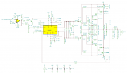
Attached is the schematic of the circuit (without the output relay connections, I can post it if you ask), output MOSFETs are BUZ900P/905P pair and drivers are MJE15032/15033. I've also included a VI limiter and a thermal shutdown network driving the mute pin, but I don't know if it works since I've never tested it, its designed for Tsink_max = 70 ºC.
Best regards,
Daniel
thank you very much for clarifing my question Andrew T, I will use only one heatsink for both channels,
What are the values used for Tsink (Heatsink maximum temperature) do you use in you calculations?
Rsink_ambient = (deltaT/Pdmax) + Rcase_sink + Rjunction_case [ºC/W]
Pdmax = sqr(Vcctotal)/(2*sqr(pi)*RLmin) [W]
What is the value of Rcase_sink? Can you clarify this? I've seen values between 0.2 and 0.5 ºC/W.
Where the number of transistors is taken in account?
PS:
Attached is the schematic of the circuit (without the output relay connections, I can post it if you ask), output MOSFETs are BUZ900P/905P pair and drivers are MJE15032/15033. I've also included a VI limiter and a thermal shutdown network driving the mute pin, but I don't know if it works since I've never tested it, its designed for Tsink_max = 70 ºC.
Best regards,
Daniel
Attachments
You'd probably get quite a bit out of reading my Taming the LM3886 Chip Amplifier - Thermal Design page.
As far as mounting the transistors on the heat sink, I suggest you learn how to drill and tap holes in aluminum. It not hard but does require a bit of practice.
~Tom
As far as mounting the transistors on the heat sink, I suggest you learn how to drill and tap holes in aluminum. It not hard but does require a bit of practice.
~Tom
Hi everyone,
The problem is that I never worked with metals and I don't know how many transistors this heatsinks can have attached. And how to attach them?
There is any heatsink with pre drilled holes for 14 transistors? Where I can get it?
Best regards,
Daniel
The transistors need bolting to the heat sink.
You can drill 2.5mm holes then tap the threads with a M3 tap or drill 4mm holes and put M3 bolts right through with nuts on the other side.
The transistors need insulating from the heat sink or they will short out.
You can buy insulators for your transistors from most electronics suppliers.
The transistors you are using are all single hole mount which is the easiest.
I recently used To3 packages on a bipolar design and had to use a pcb as a drill template for the 4 holes for each transistor.
When you drill the holes make sure you de-burr all holes or any burr or swarf will cut through the insulators and short out your transistor.
Last edited:
Hi everyone,
Thanks for the tips Nigel, the case of the transistor is connected to gate, source or drain?
After some calculations, and reducing Tamb to 25 ºC, I still have Tsink_max = 70 ºC I think I need something like:
2x SK56-100-SA Fischer Elektronik (one for each channel)
2x SK56-150-SA Fischer Elektronik (one for each channel)
1x SK56-200-SA Fischer Elektronik (for both channels) assuming a duty cycle of 50%
Those heatsinks are very expensive, are there any alternatives?
To evershumi:
Do have any ideia of the thermal resistance of your heatsink.
Best regards,
Daniel
Hi everyone,
Thanks for the tips Nigel, the case of the transistor is connected to gate, source or drain?
Best regards,
Daniel
The drain is connected to the case of vertical mosfets like yours.
The source is connected to the case on lateral mosfets like ALF16N16W

- Status
- This old topic is closed. If you want to reopen this topic, contact a moderator using the "Report Post" button.
- Home
- Amplifiers
- Chip Amps
- Choosing an heatsink for my first amplifier