I've still got a slight glitch happening. I'll post a couple screen shots in the morning. There's still a little upscale 500kHZ tick on the waveform . It's very low voltage. I don't know if it's an issue or not.
"upscale tick" ? = parasite that bites a rich mans dog that lives in a mansion ? 😀
OS
original concept amp ....
Anything short of the attached arrangement is sub-optimal (below).
(how you should build a slewmaster) .... 😀
This thing is now so silent and stable , even I'm surprised.
All the other projects I've tried in 6 years around here don't hold a candle to this.
I'm scared to really "let it go"( 200W+) before I finish this (below 2-protection).
The amp pictured survived blown caps , a bad IPS ( mis - stuffed Kypton)
and a probe slip .... still keeps on ticking.
With a protection system - 20+ years of service - guaranteed ! 🙂
PS - thanks for those real good 22u/100V'ers, Jeff !
They are 2X the size of the cheap black ones , and fit perfect , as well !!
Edit - I've been using that 10" sub as a real load for these - the Kypton
does the bass like a champ now. NO issue here ... spook = kypton
OS
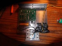
Attachments

Last edited:
I picked the cap with the highest temperature rating to sit that close to the output devices. That's why they are a little larger I think.Anything short of the attached arrangement is sub-optimal (below).
(how you should build a slewmaster) .... 😀
This thing is now so silent and stable , even I'm surprised.
All the other projects I've tried in 6 years around here don't hold a candle to this.
I'm scared to really "let it go"( 200W+) before I finish this (below 2-protection).
The amp pictured survived blown caps , a bad IPS ( mis - stuffed Kypton)
and a probe slip .... still keeps on ticking.
With a protection system - 20+ years of service - guaranteed ! 🙂
PS - thanks for those real good 22u/100V'ers, Jeff !
They are 2X the size of the cheap black ones , and fit perfect , as well !!
OS
I tried a few more inputs last night. The combination of transistors on my output board has made everything work better. Turning off my signal generator used to always trip my protection boards. Not any more.
4 IPS's
All are at 5.3-5.4ma VAS.
Swap em' out to the OPS , stabilizes to a perfect 15mv Re ... every time
any temperature ,even after playing loud bass through the sub.
I increased the symasui compensation cap to be safe , it settles within 2 seconds.
-that servo "issue" seem to be a "non-issue".
the sym also makes great bass.
before I listen full range - need my solid state relays ...
I have a feeling I have a few $$4K "audiophile amps" in front of me !!
OS
I picked the cap with the highest temperature rating to sit that close to the output devices. That's why they are a little larger I think.
I tried a few more inputs last night. The combination of transistors on my output board has made everything work better. Turning off my signal generator used to always trip my protection boards. Not any more.
After getting my "bugs" out ... these are killer amps.
I can shake the house and they barely break a sweat ! 😱
What I've heard at "reasonable volumes" , all these ips's are
better than OEM ... easily !
I'm going to need your help to get that protection board going. You tested it ?
As you see , I'm committed (the milling is done) 😀 .
Edit - having the slightly faster/lower Cob driver makes for a happy OPS !!
OS
Oh , another thing I've noticed ... you can ground
these amps wrong and they still don't hum ?? 😕
OS
these amps wrong and they still don't hum ?? 😕
OS
Hi OS about the "blue led" in Krypton, more what i found in blue has a Vf over 3V at near 3.5V. No matter the color the led has to have a Vf at 2.7V area? My concern is on a combo 5OPS board and +/-50Vdc Rail.
Marc
Marc
I have the latest protection board running. It's working well so far. I haven't put a huge load on the SS relay yet. I'm going to run a huge overload through one and see what happens. I want to make sure it blows open, not dead short on meltdown.After getting my "bugs" out ... these are killer amps.
I can shake the house and they barely break a sweat ! 😱
What I've heard at "reasonable volumes" , all these ips's are
better than OEM ... easily !
I'm going to need your help to get that protection board going. You tested it ?
As you see , I'm committed (the milling is done) 😀 .
Edit - having the slightly faster/lower Cob driver makes for a happy OPS !!
OS
Now that my oupoutput board is more stable I'm going to go through and fine tune all my input boards. I had a Wolverine in it last night that played great but the blue LED wasn't lit.
Oh , another thing I've noticed ... you can ground
these amps wrong and they still don't hum ?? 😕
OS
I've noticed this on a couple other amps too. Valery's CFA-CFPx2 amp is dead silent no matter what I do. Tubsumo buzzes no matter what.
Hi OS about the "blue led" in Krypton, more what i found in blue has a Vf over 3V at near 3.5V. No matter the color the led has to have a Vf at 2.7V area? My concern is on a combo 5OPS board and +/-50Vdc Rail.
Marc
My blues are all 2.67V. Any Vf over 2.3V will do . GaN leds all do 2.6-3.3V
depending on the source.
Even a green will work for all the hawksford based -slewmaster VAS's.
For a 50 V rail ... your only concern is the zener dropping resistors. Nothing
much else ... I test mine at 40 /63/73 V , all is good. 🙂
OS
You got the blue reversed? It adds 2.67V to the 12-15V zener referenceI have the latest protection board running. It's working well so far. I haven't put a huge load on the SS relay yet. I'm going to run a huge overload through one and see what happens. I want to make sure it blows open, not dead short on meltdown.
Now that my oupoutput board is more stable I'm going to go through and fine tune all my input boards. I had a Wolverine in it last night that played great but the blue LED wasn't lit.
for the cascode.
I added it to the design to confirm the cascode operation and to offset the
voltage drop of the emitter follower cascode source (2 birds with 1 stone) 😀
(make sure you have the option solder bridge jumpered. (opt 1-
"a"side and opt 3 bridged) ... it's my "test dog" !!
OS
You got the blue reversed? It adds 2.67V to the 12-15V zener reference
for the cascode.
I added it to the design to confirm the cascode operation and to offset the
voltage drop of the emitter follower cascode source (2 birds with 1 stone) 😀
(make sure you have the option solder bridge jumpered. (opt 1-
"a"side and opt 3 bridged) ... it's my "test dog" !!
OS
It was lit before I set the CCS and offset. What is the proper setup for CCS. I set it by the voltage drop (3.6V) on R10. I don't remember if I matched any transistors when I assembled it. Could that be the cause? Offset didn't zero very well. I was getting around 4.5mA between PD and ND with 100R resistors to NFB. Should I raise that?
It was lit before I set the CCS and offset. What is the proper setup for CCS. I set it by the voltage drop (3.6V) on R10. I don't remember if I matched any transistors when I assembled it. Could that be the cause? Offset didn't zero very well. I was getting around 4.5mA between PD and ND with 100R resistors to NFB. Should I raise that?
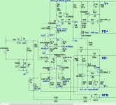
(below) is the present "test dawg".
If you use the 12V zener , the cascode will be about -14v.
If your blue led is out , your cascode is not referenced. I added the voltages
to the schema. My real one measures exactly the same with 40 or 73v rails.
Edit , CCS current or offset matters not (for proper operation) , I can set mine anywhere with little effect ..
other than changing my LTP I or getting 100mv offset ???
I'm only using D4 for a saturation clamp , as well.
OS
Attachments
Last edited:
(below) is the present "test dawg".
If you use the 12V zener , the cascode will be about -14v.
If your blue led is out , your cascode is not referenced. I added the voltages
to the schema. My real one measures exactly the same with 40 or 73v rails.
Edit , CCS current or offset matters not (for proper operation) , I can set mine anywhere with little effect ..
other than changing my LTP I or getting 100mv offset ???
I'm only using D4 for a saturation clamp , as well.
OS
Thanks. I'll check it out tonight.
Blue leds typically have a Fv 3.5v @20mA when you look in the catalogs, in kypton the leds current are about 5mA so Fv Will be around 2.6v, so it's okay to buy 3.6v leds?
Blue leds typically have a Fv 3.5v @20mA when you look in the catalogs, in kypton the leds current are about 5mA so Fv Will be around 2.6v, so it's okay to buy 3.6v leds?
Kypton blues are @ 2.3ma I . If you went lower on the trimmer , about all you
could pass would be 3.5ma.
As I said before , 2.3 - 3.5V does not matter , besides losing some rail
"headroom" through the cascode. LED I is set through the trimmer/resistor
combo , so LED type does not matter here , either.
And If you use >70V rails , it won't matter !
OS
I'm going to be running 63V rails. I'm trying to decide the safest route. Should I try higher voltage next or install all my outputs first?
I'm going to be running 63V rails. I'm trying to decide the safest route. Should I try higher voltage next or install all my outputs first?
I "loaded" all mine at the 40V level. Heatsinks got a little warmer (Vceo) and
bias changed slightly at 63/73V , but that's all .
OH! I forgot ... all my 35V caps exploded when i moved up to 63V 😱😱 😀.
OS
I've loaded mine at 40V into 4R. I think 4R at 63V will be too much even for the MT200s so I'll add some more outputs first.I "loaded" all mine at the 40V level. Heatsinks got a little warmer (Vceo) and
bias changed slightly at 63/73V , but that's all .
OH! I forgot ... all my 35V caps exploded when i moved up to 63V 😱😱 😀.
OS
I've loaded mine at 40V into 4R. I think 4R at 63V will be too much even for the MT200s so I'll add some more outputs first.
4R @ 3-pair mt-200 is the heftiest amp on all the forum for 3 pair !!
My sub amp could easily do 500W/4R with a sufficient PS !
They use those MT-200's - single pair 70V rails for 125W receivers.
PS - you just might hit 100ms SOA with a single pair @ 4R/60V.
OS
- Home
- Amplifiers
- Solid State
- Slewmaster - CFA vs. VFA "Rumble"