Member
Joined 2009
Paid Member
... before this thread mutated....
Attachments

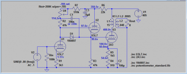
It will be this one, attached.Goldenbeer - what schematic did you finally settle on?
Maybe I'll add the L-W hum cancellation scheme at a later stage.
Attachments
It will be this one, attached.
Maybe I'll add the L-W hum cancellation scheme at a later stage.
If you use the LF hum cancellation, and for it to work properly, C2 should go to B+, not to common (20uf should be plenty, so you can use a film cap). The signal current circulates in the loop comprising B+, output tube, transformer primary, B+. Power supply current and noise, circulates through a loop comprising B+, transformer primary, R5,4, and common. Part of the noise component can be injected at the top of R1, so it occurs in anti phase at the plate of U1, and consequently the grid of U3.
If you do it this way, you don't need C3 either. PS noise at U1 plate, is already in anti phase to the noise signal at R1 and adds to the injected anti phase noise. No problem, because you simply adjust the amount of signal from R5,4 to get a null at the amp output.
As mach1 and 45 noted, few people understand what Loftin and White were doing, and simply assume that any direct connected amp is a Loftin/White amp. They've missed the whole point, and the subtle elegance of the original design.
Sheldon
Actually, I't get rid of R7 as well, and just increase the value of the divider resistors on the plate of U1 (maybe two 300k). If you need to adjust the current for U1, simply adjust R1. One of the beauties of this topology, is that once you get all the values adjusted it remains very stable over the lifetime of the tubes.
Last edited:
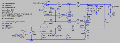
How do you round the decimal points on your data labels?
I found a formula to round but its a PITA to do it with every label.
round($*1)/1 for voltage
round(I(R1)*1k)/1k for current
Its going to take me a couple more years to grasp this one. 😀
I found a formula to round but its a PITA to do it with every label.
round($*1)/1 for voltage
round(I(R1)*1k)/1k for current
If you use the LF hum cancellation, and for it to work properly, C2 should go to B+, not to common (20uf should be plenty, so you can use a film cap). The signal current circulates in the loop comprising B+, output tube, transformer primary, B+. Power supply current and noise, circulates through a loop comprising B+, transformer primary, R5,4, and common. Part of the noise component can be injected at the top of R1, so it occurs in anti phase at the plate of U1, and consequently the grid of U3.
Its going to take me a couple more years to grasp this one. 😀
Last edited:
Yes. I've tried to convince more people to try this circuit, unsuccessfully till now. Still don't think you need that trimmer in the U1 plate circuit. It carries current, so could get noisy over time.
Sheldon
Also, I should note that Darius's addition of the bootstrapped follower is an inspired one. It allows much wider choice of input tubes. Without it, the range of input tubes is narrow. That's because both input and output tube operating points are tightly constrained by each other.
Sheldon
Also, I should note that Darius's addition of the bootstrapped follower is an inspired one. It allows much wider choice of input tubes. Without it, the range of input tubes is narrow. That's because both input and output tube operating points are tightly constrained by each other.
Last edited:
Its going to take me a couple more years to grasp this one. 😀
Nah. Draw the current loops in different colors. Then label the signal phase, through the signal path. Do the same, in a different color, for PS noise. Look at that picture for awhile.
Sheldon
Still don't think you need that trimmer in the U1 plate circuit. It carries current, so could get noisy over time.
The sole purpose of that trimmer is to adjust the U1 plate voltage. It should be pretty close to 99~100V, since this determines the bias of the 2A3. And Rp varies quite a bit at low anode currents. Tube scatter or ageing might throw this off.
Maybe I'll get rid of the trimmer once I built the amp and rolled some tubes while checking the bias. Remains to be seen.
GB
Fair enough. That could be an issue if the tubes vary a lot. I think you may find it pretty easy to get tube combinations close enough, without too much sorting. If your power supply isn't over spec'd by a bunch, as the bias on the output tube raises, power supply voltage sags a little. That will bring the input tube plate voltage down. I've found parameters fall pretty much in line, as I've tested different combinations of input/output tubes (7n7/801A). Pretty well self balancing. Curious to see your results.
You could probably sim it with some tube variation, but not with a pure voltage source - maybe just a series resistor that models close to your supply voltage sag?
Sheldon
Last edited:
It will be this one, attached.
Maybe I'll add the L-W hum cancellation scheme at a later stage.
Hi, goldenbeer,
So you opt for cascoded bootstrapped stage with cathode follower.
Did you try to simulate in LTSpice how bootstrapping affects THD level? I did THD simulation of PP amps and numbers were very close to reality.
Did you try to simulate in LTSpice how bootstrapping affects THD level? I did THD simulation of PP amps and numbers were very close to reality.
Simulation of the pre stage gives ~.2% THD at full power, depending on tube model, with H2 dominating. At such low level however I wouldn't put too much faith in these figures, and the THD of the pre-stage is dwarfed by that of the 2A3 anyways.
Zout sims at ~1.1kOhm with ~2mA plate current thru the bootstrapped follower, which should be fine to drive the 2A3.
Rgds,
GB
That is the results for an unloaded gain stage. To get a more accurate view of what is going on, add a cap coupled resistor with a value equal to the impedance of the stage you will be driving.
Although, if it is a cathode or source follower it's impedance may be negligible.
Although, if it is a cathode or source follower it's impedance may be negligible.
Total Harmonic Distortion: 0.002928% at 120VPP output.
Don't believe that for a second.
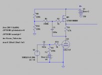
I simmed a 6SL7 gain stage.
Total Harmonic Distortion: 0.002928% at 120VPP output.
Sims are sims, but it's clear to see that there's much better voltage amplification available from 6SL7....
The 0.00...% are a numerical glitch of the simulation.
By playing around with the resistor values I can get 0.05% from my stage shown above. After adjusting the resistor values to more reasonable values which should result in lower THD by conventional wisdom, the sim results rise to .1%~.2% THD, depending on tube spice model.
Bottom line, tube models are unreliable at low THD figures. Even more so at low anode voltages, where curvature is more pronounced.
Now back to your circuit, I know there are better THD values to be had from a 6SL7, but the challenge here is 1. to use low plate voltage not to burn off too much power in the 2A3 cathode resistors, and 2. to use conventional tube technology thruout and not to use any ss parts as active loads in the circuit.
Cheers
GB
I simmed a 6SL7 gain stage.
Total Harmonic Distortion: 0.002928% at 120VPP output.
Sims are sims, but it's clear to see that there's much better voltage amplification available from 6SL7 than 0.2% THD.
Hi, MrCurwen,
Do you bias 6SL7 with negative voltage on the grid instead of positive on cathode with resistor, in order to get max gain and no Rk bypass capacitor? Didn't seen this hack before in per-amplifiers. For power stages its common, however.
Last edited:
If you use the LF hum cancellation, and for it to work properly, C2 should go to B+, not to common (20uf should be plenty, so you can use a film cap).
Just one note, I toyed around with the simulation, and 47uF is the minimum I recommend for the "ultrapath" cap. Go below, and output impedance in the lower frequencies shoots up.
Maybe Loftin and White were able to get away with smaller caps because they didn't care about f<50Hz.. Without the constraints of yesteryear, we should aim for something better today, and 47uF even in foil doesn't seem over the top for me.
Oh, one additional advantage of the ultrapath cap is that the tube's signal current no longer circulates thru the psu, so no more sag on transients and filtering becomes a breeze.
Good info. I sized the ultrapath cap on my amp, looking at noise cancellation and frequency response. Going larger didn't benefit in that respect (though didn't hurt either). My 7n7/801 only puts out about 1 watt, so I haven't used the amp to cover the full range, except for headphones, but good to know for builders who will power a speaker that covers the full range.
I'm glad to see you pursuing this. The true L/F won't become a common topology, as designing the stages independent of one another will always be easier. And its not the most power efficient way to go. But grasping L/W's insights and building a version, has been my most gratifying project. It has a beautiful symmetry, all elements working together.
Sheldon
Last edited:
Hi,
I have just found one interesting project on the web that is maybe relevant to this project, it uses one 2A3 per channel and at 5WATT output claiming 0,211% distortion without any feedback used and without any gain stage - I find it hard to believe!
Link: Untitled
Author have not yet released drawing of his new design, I hope it will so we can all enjoy 2A3 sound at normal sensitivity speakers!
Attachments

- Status
- Not open for further replies.
- Home
- Amplifiers
- Tubes / Valves
- 3 direct coupled 2A3 amps