Does a schottky function properly when wired in a revers bridge rectifier mode in order to give a negative voltage supply? If so, is it superior in function to a standard silicon rectifier, or are all its benifits facing the wrong direction. I can't seem to find anything praising its virtues as a valve (tube) negative bias supply rectifier, nor anything in the split rail supply for IC's. Any opinions, or insight?
I would say in the employ that you suggest, there is no benefit. Shottky are fast recovery devices ideal for SMPS use.
If the input to the rectifier swings between +Vsine and -Vsine, the output of the rectifier is -Vsine {neglecting the diode drop for a moment}. At the crest of the input wave the cathode is +Vsine and the anode is -Vsine. The voltage across the diode is (2*|Vsine|). So you need a diode whose peak inverse voltage rating is at least (2*|Vsine|) + safety_margin.
Solid state designers usually prefer to include enormous safety_margin, mostly because the extra cost is very small. In solid state equipment, rectifier diodes are selected with peak inverse voltage ratings from (4*|Vsine|) to (20*|Vsine|).
This is bad news for Schottky lovers who want to rectify high voltages. Schottky diodes are usually designed with relatively low peak inverse voltage ratings (below 150 volts). Some high voltage Schottkys are available, but their forward voltage drop is higher, negating one of Schottky's big advantages.
If a peak inverse voltage rating of 1000V is sufficient, I suggest the 10A07 non-Schottky rectifier from Diodes Inc (data page). It's got relatively low leakage, relatively low forward voltage drop, relatively high current / high power rating, and relatively low capacitance. It does NOT have relatively fast reverse recovery time; but in a 100Hz fullwave rectifier circuit, this is not a problem.
Last edited:
Surely with a bridge rectifier this is not the case, as the join between the two diodes at the input of the Vsine will not be higher than the diode drop voltage when the sine swings over to the other direction. So peak inverse voltage rating only needs to be (Vsine + VF) + safety margin. But that wasn't really my inquiry, I was woundering if the fast cutoff, if facing ground in a negative supply bridge rectifier is noticable, I would assume the two diodes connected between smoothing reservoir and supply transformer might imput less shutoff ring injected into the parallel transformer widigs that might be imparted upon the heater supply, and then into the valves. I realize this might be minimal in effect.If the input to the rectifier swings between +Vsine and -Vsine, the output of the rectifier is -Vsine {neglecting the diode drop for a moment}. At the crest of the input wave the cathode is +Vsine and the anode is -Vsine. The voltage across the diode is (2*|Vsine|). So you need a diode whose peak inverse voltage rating is at least (2*|Vsine|) + safety_margin.
There seems to be a dearth of physically measured data from real power supplies, showing the effect (or non-effect!) of various kinds of diodes, upon the transformer secondary "ringing". Some people postulate that Schottky diodes probably ought to be an improvement over silicon diodes. Other people postulate that "soft recovery diodes" (having tb > (ta/2)) probably ought to be an improvement over silicon diodes. Yet others suggest that HEXFRED diodes probably ought to be an improvement over silicon diodes. And there are some people who suggest that Silicon Carbide diodes ought to be best. But physically measured data from real power supplies, showing the effect of different kinds of diodes, is hard to find.
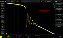
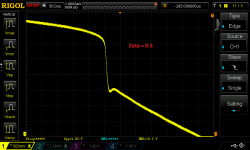
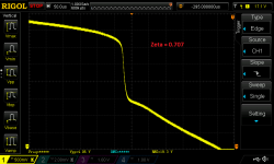
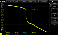
However, many people DO agree (and measured data is easy to find), that you can completely eliminate transformer secondary "ringing" no matter what diodes are used. Just connect an RC snubber to set the damping ratio of the transformer secondary's parallel RLC circuit, greater than 0.5-1.0. This completely annihilates ringing. I've attached some measurements made by diyAudio member DNi and posted to another thread in the Power Supplies forum, showing this. The oscilloscope is set to trigger at the instant when the rectifier diode turns off. As you can see, when the damping factor Zeta is set to an appropriate value, ringing is removed. You can google for "Hagerman AND snubber" or "Quasimodo AND snubber" to learn much much more.
Here is the datasheet of a diode which specifies and guarantees the soft-recovery parameters "tb" and "ta". See Figure 1 and the table of specifications on page 2.
_
Attachments
Thank you Mark, I was aware of the use of capacitors to lower the frequency of the ringing, but the damping as explained by Hagerman is of great interest, and I thank you for making me aware of it. I will have to get an inductance meter. Hagermans example still has a residue initial pulse, and surly it is the amplitude of this the switchoff of a diode can effect. But this still leaves my initial question unanswered, and that is how, if at all, is the working of a schottky diode affected by the fact that it has its cathode rather than ita anode conected to the supply source, and the reservior is at its anode.
Have a look at DNi's waveforms attached to post #5 of this thread. These are measured on actual diodes in an actual linear power supply with an actual transformer (they aren't simulations). Do you see "a residue initial pulse" on the Zeta=1 waveform?
As for your unanswered initial question, I recommend you build a test-jig and obtain the answer experimentally.
As for your unanswered initial question, I recommend you build a test-jig and obtain the answer experimentally.
- Status
- Not open for further replies.
- Home
- Amplifiers
- Power Supplies
- Schottky negative power supply?