The Goldmund is a Class AB amp, with a few mA bias to the A class region.What the heck are you talking about? Class B is defined by no current, zero bias, at no signal.
Class AB has some bias at zero signal to avoid crossover distortion.
But anyway as you wrote:
🙂This thread sucks...
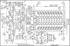
#22 funny way of making a balanced amplifier. two separate input amplifiers summed in a common VAS. Never seen this concept before.
#22 funny way of making a balanced amplifier. two separate input amplifiers summed in a common VAS. Never seen this concept before.
Not true, front-end is parallel entirely and summed at VAS. Balanced input at Accuphase is usually done with OP amps in front of the power amp in a instrumentation way.

Last edited:
Lazy look at The schematic, two separate inputs summed at the VAS,
I would like to make a ballanced input to my diamond input CFA, but I find the accuphase a little overboard. Using op amps instrumention way, would for sure mean a quality loss. Here iam not so sure.
I would like to make a ballanced input to my diamond input CFA, but I find the accuphase a little overboard. Using op amps instrumention way, would for sure mean a quality loss. Here iam not so sure.
Lazy look at The schematic, two separate inputs summed at the VAS
Nope, look carefully, both diamond stages are in parallel and afterwards VAS stages summed.
Both positive inputs paralleled as well as negative inputs. This is done, as explained by Accuphase, because of noise reduction and lower THD.
What is Yamaha anything to do with Accuphase? From my experience, Yamaha is no where high end amplifiers by any stretch before!!!
Lazy, I think we are saying the same.. One input rail to rail for the posetive input, and one for the negative, Then they are summed at the VAS. Ohh I see what you mean, both are driven by the same input, the other is then used as a reference.
Difficult to interpret the feedback ??.
Difficult to interpret the feedback ??.
Last edited:
Two front-ends with paralleled inputs and paralleled VAS outputs - this is something Accuphase used a lot.
In one (or maybe more) of their amps - I don't remember the exact model at the moment - they even used three front-ends in parallel. 2 channels = 6 front-end modules 😱 Worth trying to build some simple CFA front-end and see what effect paralleling of 2 or 3 of them gives in terms of noise and distortion, with practical measurements 😉
In one (or maybe more) of their amps - I don't remember the exact model at the moment - they even used three front-ends in parallel. 2 channels = 6 front-end modules 😱 Worth trying to build some simple CFA front-end and see what effect paralleling of 2 or 3 of them gives in terms of noise and distortion, with practical measurements 😉
What is Yamaha anything to do with Accuphase? From my experience, Yamaha is no where high end amplifiers by any stretch before!!!
Yamaha was making high end amps before Accuphase really even existed as we know it now. Have a look at the Yamaha B1 especially - this amp is still unique and not equalled by anything else ever. Later B2, B3, then the A1. Out of the newer offerings, MX-2000, MX-10000.
Ha ha, when I hear Yamaha, I think electric piano, electric drums and other musical instruments. I even had a guitar amp by Yamaha.
Funny this paralleling of front-ends, Why not just make one front end and then parallel the transistors/resistors. I believe that would yield the same in terms of noise reduction.
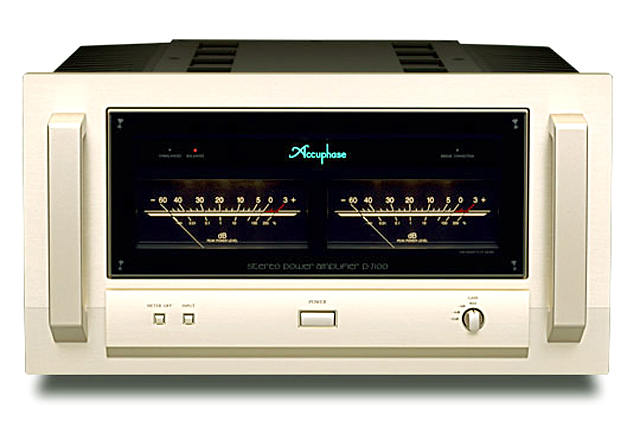
P-7100
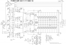
Interesting, that the front end running from+/-60V and the output stgae from+/-75V. It means lot of heat loss...
Sajti
I was thinking about lowering the voltage of my front end also. My rational is keeping the collector base voltage of the power transistor at least 10V to keep the CCB low.Interesting, that the front end running from+/-60V and the output stgae from+/-75V. It means lot of heat loss...
Sajti
What is the power output of this amp. Why keep the rail voltage so high? So many output transistor!!! Are they running at very high quiescent current to keep the amp running in Class A in lower volume?
The emitter resistor is 0.47ohm. So if they follow Oliver's condition RE=re', then each transistor is biased at 50mA. 11 power transistor implies quiescent current of 550mA.
Last edited:
It can be traced back to their mission: Accuphase was formed by a team of designers from Kenwood that wanted to make audio gear without unnecessary compromises and penny pinching. They used so many output devices in the P-7100, because that amplifier was designed to deliver a straight power curve into any impedance that it would encounter. The P-7100 was around 135W into 8 ohms and 1000W into 1 Ohms. It isn't needed, because all of the speakers that approached 1ohms are obsolete; none are made that way anymore. However, it is without compromise and if the owner wanted to run multiple speakers from one channel, he or she could.I was thinking about lowering the voltage of my front end also. My rational is keeping the collector base voltage of the power transistor at least 10V to keep the CCB low.
What is the power output of this amp. Why keep the rail voltage so high? So many output transistor!!! Are they running at very high quiescent current to keep the amp running in Class A in lower volume?
The emitter resistor is 0.47ohm. So if they follow Oliver's condition RE=re', then each transistor is biased at 50mA. 11 power transistor implies quiescent current of 550mA.
- Status
- Not open for further replies.
- Home
- Amplifiers
- Solid State
- Accuphase amps