Looking for an opinion from any RF experienced/knowledgeable folks.
Will be building a simple full-wavelength loop antenna - the well known square of roughly 130" length, quad cubical. Googling around, I found a rather interesting derivative of the normal design here:
http://www.wryr.org/Antenna_instructions.pdf
Basically a loop with the feed taken from the center. Not clear if the part from the loop to the center is done with 300 ohm ribbon or if not, what the spacing is.
The claim that this simple mod improves the gain by 3dB is outlandish but easy enough to verify. What baffles me is that they claim 300 ohm impedance, when a normal loop is closer to 75.
Can someone knowledgeable give an assessment of what, if anything, this mod does to the characteristics of a loop antenna? Thanks.
3dB for circ polarisation only is hardly worth the effort.
Altering the feed points changes the input impedance.
The instructions are extremely difficult to follow, IMO.
I'll go get the ARRL antenna book.
Altering the feed points changes the input impedance.
The instructions are extremely difficult to follow, IMO.
I'll go get the ARRL antenna book.
I can't find the antenna book ATM.
If you leave an open circuit at the bottom corner you can feed 75 ohm there, that's the normal arrangement, although you can put the feed at the side. Are you particularly anxious to use 300 ohm?
If you leave an open circuit at the bottom corner you can feed 75 ohm there, that's the normal arrangement, although you can put the feed at the side. Are you particularly anxious to use 300 ohm?
Basically a loop with the feed taken from the center. Not clear if the part from the loop to the center is done with 300 ohm ribbon or if not, what the spacing is.
The claim that this simple mod improves the gain by 3dB is outlandish but easy enough to verify. What baffles me is that they claim 300 ohm impedance, when a normal loop is closer to 75.
I would agree with you that the impedance will be closer to 75 ohms at the the central feed point , conceptually it's an unfolded 75 ohm T dipole (twin lead thingy) with a much greater loop area to increase the gain.
this one has better documentation and analysis, it's a 300 ohm, but needs a transformer and a couple of baluns to properly tune and align the thing. I think of it as a folded gamma matched ( unequal feed point ) T dipole with single wires.
The claim that this simple mod improves the gain by 3dB is outlandish but easy enough to verify
really, how?
sure 3db gain over a horizontal dipole for a polarized transmission, with 3 other things to bugger it up. > if you can align it , match the impedance ,and prevent signal loss to the unbalanced coax ground feeding it! ie use the baluns for that and measure the impedance.
outlandish I think not
Last edited:
really, how?
I just built a plain square 1 lambda loop today, it performs ok. I can modify it to the proposed center feed configuration and compare. I have a number of tuners available with a variety of signal meters.
sure 3db gain over a horizontal dipole...
That author claims 3db over the same loop, only by changing to center feed.
The Brian Beezley one looks interesting and I'm sure it performs well, but it's considerably larger than a one-lambda loop. The sides are 4ft.
It isn't a cubical quad, modified or otherwise.
It is a modified loop. Whether it works or not I can't say, but I suspect it has no special properties. It appears to be an attempt to receive both polarisations (V and H) from a single loop by connecting the two feed points together via a phasing and matching section of twin line. The snag with this if it works is that you have to ensure that you are set to receive the correct circular polarisation; if not you get a null instead of a 3dB boost.
For most people a folded dipole is better. Further away use a Yagi.
The snag with this if it works is that you have to ensure that you are set to receive the correct circular polarisation; if not you get a null instead of a 3dB boost.
And how does one ensure? Please explain.
For most people a folded dipole is better. Further away use a Yagi.
I have to say the loop as built (without center feed at this time) is only marginally better than a standard $2 dipole T made of 300 ohm ribbon. But it has some advantages, for example it's easier to handle and orient. It's also less sensitive to human bodies in close proximity.
And how does one ensure? Please explain.
The majority of FM broadcast antennas in North America are circularly polarized. The best receive orientation for you will probably be location specific and related to multipath.
There are two circular polarisations, left-hand and right-hand. You need to find out which the transmitter uses and then find out how to wire the antenna to receive this.
FM transmitters use circular polarisation so that they can be received on either vertical (e.g. car or portable) or horizontal (e.g. good home system with loft/roof) antennas; the intention is not that receivers will use circularly polarised antennas.
FM transmitters use circular polarisation so that they can be received on either vertical (e.g. car or portable) or horizontal (e.g. good home system with loft/roof) antennas; the intention is not that receivers will use circularly polarised antennas.
Right. But as Beezley explains in the writeup quoted in post #4 above, they are mirror image, i.e. an antenna properly oriented to receive right circ. pol. from the south is the same as left circ. pol. from the north.
So a simple matter of turning it through a full 360 degrees to find the best orientation.
So a simple matter of turning it through a full 360 degrees to find the best orientation.
FM transmitters use circular polarisation so that they can be received on either vertical (e.g. car or portable) or horizontal (e.g. good home system with loft/roof) antennas...
I'm sure you meant antennas, none the dozens of commercial FM plants I've been involved with could alter polarization from the transmitter.
No. I was using "transmitter" in the sense of everything at the transmitter site, not just the actual RF generator. It would be wrong to say "antennas", as in some cases circular polarisation is obtained by phasing separate antennas - so the emitted polarisation comes from the whole antenna system (including feeders) not just the antennas themselves.
It would be wrong to say "antennas", as in some cases circular polarisation is obtained by phasing separate antennas....
It's standard broadcast industry terminology in North America. 'Antenna' is normal shorthand for 'antenna systems', which in the case of single feeder systems includes all the elements at the end of the main cable; power splitters, jumpers, panel and dipoles as applicable. You could quibble that in the split, dual array systems built for redundancy 'antenna' should include the feed lines since difference in length impacts beam tilt. It's rarely done since it's so vague.
Phasing in the most common FM antennas (Sira, Kathrein, etc.) is done at the dipoles mounted at the centre of each panel. Transmitters have exactly zero impact.
transmitter = (sending end ) the whole ball of wax at the other end of an FM receiver AND antenna(s) end.
sheesh rdf, quit quibbling over a word not helpful to the OP
sheesh rdf, quit quibbling over a word not helpful to the OP
Polarization is determined by the antenna system. Period. End of story. It's not wrong to say 'antenna' and maintaining otherwise requires correction no matter who's wrong. Now, if you've also built nearly a dozen commercial FM sites and managed two of the largest multi-tenant plants in your country a conversation about regional variances in broadcast technical language could be an interesting topic for another thread.
look at it from the other end some time , perhaps yer too close to The Transmitter. LOL
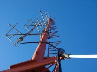
RDF how many antennas does it take for a typical FM broadcast antenna and how do you align it ? any pictures of a tower would help.
I reckon its trying to get the most coverage with a fixed amount of power at the final.
RDF how many antennas does it take for a typical FM broadcast antenna and how do you align it ? any pictures of a tower would help.
I reckon its trying to get the most coverage with a fixed amount of power at the final.
Last edited:
I reckon its trying to get the most coverage with a fixed amount of power at the final.
There really is no typical, examples from a low power single V dipole to a couple hundred foot vertical array of large panels dissipating 100 kW are easy to find. FM antennas are a really interesting combination of art and science optimized to tower type; leg vs. face mounting, icing effects, guards etc.. Final field and manufacturer confirmation testing of calculated parameters aren't uncommon.
Broadcast engineering consultants typically target maximum field strength of the licensed coverage area, these days directional builds are as common as omnidirectional. The good old days of lighting it up for maximum reach are long gone in North America, though my understanding is at least until recently the 'biggest transmitter wins rule' still held in Greece for example.
what's icing in Canada LOL
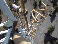
This one looks robust
I wonder about the feed points here
1/4 wave stub grounds?
rdf > how is the splitter implemented and is phase critical?
This one looks robust
I wonder about the feed points here
1/4 wave stub grounds?
rdf > how is the splitter implemented and is phase critical?
Attachments
Last edited:
what's icing in Canada LOL
Pretty but the ice drops can crush a truck (not my tower.) Who says engineering has to be boring desk work?
I never had to deal with the specifics of splitter technology, when they go the burn damage often destroys them.
Attachments

- Status
- Not open for further replies.
- Home
- General Interest
- Everything Else
- fm loop antennas