Hi,
I have had a pair of GA28F boards that have worked well until I decided that after 30 years+ they needed an upgrade (when will I learn?)....
Upshot is that now one of them has a voltage across the speaker output that slowly rises toward VCC (using +-/- 19V to test). The other has 11mV on the speaker output but there is no current when adjusting RV1.
Is anyone familiar with these and can offer some support/help/suggestions on how to get them back working?
The are not blowing the 200mA fuses put in to test, so that's something. The K134's both switch in circuit using a DMM in diode mode to test, but that's not the perfect test. There are no shorts from the transistor cans to the heatsink.
I replaced all the electrolytic caps (all the right way round🙂 ..). Also replaced the gate stoppers, R15 and RV1 as the old ones were open type and the track was very 'jumpy' when adjusting, that was when I lost current to one of them and to add to the issue I forgot to detach the speakers before adjusting 😱 , so that might help tell what's going on here.
So, hoping the season of goodwill prevails and that someone might be able to help before New Years Eve....Please help if you can.
Thanks
MM
Wasn't this the "classic" Lateral MOSFET amp of the day... if so then I'm sure we can sort this one out.
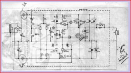
Was it this one. If so then we can look at one channel at a time. It will have to wait 'till tomorrow though 😉
You need to first check and double check your work and any replaced components.
Was it this one. If so then we can look at one channel at a time. It will have to wait 'till tomorrow though 😉
You need to first check and double check your work and any replaced components.
Attachments
Here are some other related threads which may help:
http://www.diyaudio.com/forums/soli...0w-mosfet-amplifier-power-supply-problem.html
http://www.diyaudio.com/forums/solid-state/257311-maplin-100w-mosfet-amplifier-built-1980-kit.html
Schematic found here:
maplin 100w 150w mosfet amp ga28f Download page :: Schematics Unlimited
and another:
http://www.eastmarinedrive.com/contents/non-static/audiodgoodman-content.htm
If R15 in the zobel network gets hot, it is likely that the amplifier is oscillating. Stability is reportedly improved by increasing the gate resistors R13 & R14 to 220 or 270 ohms.
Last edited:
LOL I bagged myself a lot of these modules whist they were going for nothing on ebay a few years ago. Delightfully simple and effective, but need more output devices or doubled "-D" types for bridging and/or reasonable 4 ohm efficiency....however I wander slightly off topic.
Mr. Mosfet Madness, I do not see any list or schematic of the "upgrades" you have performed, can you enlighten us?
Mooley, your schematic contains some resistor value modifications, just curiosity - was that to maintain correct operation at higher voltages, it appears to make the values 3 times larger?
I've been studying the circuit and I suspect that the module with non adjustable current but low DC offset may well be OK. The current is hugely dependent on supply voltage and so running on -/+19 volts will indeed give no quiescent current in the outputs.
Important, for testing this module I would use full supply voltage but with the safety net of a bulb tester in the mains primary. Also begin with the preset on minimum resistance as that give minimum current.
Important, for testing this module I would use full supply voltage but with the safety net of a bulb tester in the mains primary. Also begin with the preset on minimum resistance as that give minimum current.
Mooley, your schematic contains some resistor value modifications, just curiosity - was that to maintain correct operation at higher voltages, it appears to make the values 3 times larger?
I've no idea tbh, I've never built the amp. The circuit was just the one I had on my PC from years ago.
Someone had drawn the 180 ohm in at the top/bottom. Are any others different ?
The module with slowly rising DC on the output. You will have to do some basic measurements which we can advise on but first, just make sure that the gate stoppers are physically connected (no broken print) as a floating gate could cause something like this.
For both modules do not connect speakers until we are sure they are OK.
For both modules do not connect speakers until we are sure they are OK.
WOW! 🙂
Thanks for all the positive support and helpful replies. This forum is really great!
Yes it is the module you have shown Mooly. It's the original 1983 version I built at college and has the original Hitachi K135/J48 mosfets on board. Over the years R9 burnt out on both modules and was replaced with higher wattage resistors. Also the electrolytics were all changed about 20 years ago, but not since then!
I made 2 mistakes when trying to reset the current after the changes.
1. There were no fuses in the DC supply to the boards.
2. The speakers were still connected.
I now have the modules removed (still attached to the L bracket and connected to a +/-19v supply for bench testing.
I am in the UK (near Swindon, Wilts) but should be able to sort this out easily with a little advice and help.
The changes were as follows......
Remove mosfets and refit with new mica insulators and thermal paste.
Change R13 and R14 from 100R to 220R.
Change R15 from a 4R7W/W to 2x10R 2W metal film in parallel (removing inductance from the RC circuit)
Change C1 for new cap of same value.
Change C3 for new cap of same value.
Change C9 and C11 from 100uF to 220uF 63V.
Renew RV1 as the original 'open' ones were 'jumpy' when adjusting.
Only other changes were all new PSU rectifiers and filter caps which appear to be working normally.
On one module measuring resistance across R3 shows 47K in circuit, on the other board it shows a decreasing value starting in the Megohm range. Removing one leg and testing it still is 47K resistor so might point to a problem.
Thanks for the responses once again....
MM
The sound quality from these modules can never be worth the time and effort to repair them; I junked mine long ago. Re-use the transformer and heatsink.
Sounds harsh, I know ......... that's just the amplifiers 🙂
Sounds harsh, I know ......... that's just the amplifiers 🙂
Surprised to hear that RAndyB I have had several up and running and as long as you don't expect too much into low impedances found them to perform admirably. Do note however I did not use maplins pins for the supplies preferring instead to connect + - close to output device drain connections and 0v to Zobel network/speaker output trace......
WOW! 🙂
:
:
The changes were as follows......
Remove mosfets and refit with new mica insulators and thermal paste.
Change R13 and R14 from 100R to 220R.
Change R15 from a 4R7W/W to 2x10R 2W metal film in parallel (removing inductance from the RC circuit)
Change C1 for new cap of same value.
Change C3 for new cap of same value.
Change C9 and C11 from 100uF to 220uF 63V.
Renew RV1 as the original 'open' ones were 'jumpy' when adjusting.
Only other changes were all new PSU rectifiers and filter caps which appear to be working normally.
:
:
MM
Excellent, the wirewound resistors went! Maplin also made that mistake on their famous 50W board IIRC. other than that I did pretty much the same updates on all the modules I received so should be no problems there.
The single sided boards can suffer from too much solder heating even if you're careful. A pad may look connected but might be disconnected from its trace by the tiniest fracture. you can repair this by using a spare component leg (look on the floor!!) to bridge any fractures thus found....
I've no idea tbh, I've never built the amp. The circuit was just the one I had on my PC from years ago.
Someone had drawn the 180 ohm in at the top/bottom. Are any others different ?
OK. No I used the original 100 ohms value did not find any reason to change much apart from 50V electrolytics which I raised to 63V and fitted largest value now possible
A bit more checking and found a short on one module from the junction of tr1/tr2/r3 to ground. Now corrected.
With both boards fully disconnected and measuring resistance from pin4 to pin1 I get -14M on one board and +1.3M on the other. Theres a clue there I am sure 😉
MM
With both boards fully disconnected and measuring resistance from pin4 to pin1 I get -14M on one board and +1.3M on the other. Theres a clue there I am sure 😉
MM
WOW! 🙂
Thanks for all the positive support and helpful replies. This forum is really great!
Yes it is the module you have shown Mooly. It's the original 1983 version I built at college and has the original Hitachi K135/J48 mosfets on board. Over the years R9 burnt out on both modules and was replaced with higher wattage resistors. Also the electrolytics were all changed about 20 years ago, but not since then!
I made 2 mistakes when trying to reset the current after the changes.
1. There were no fuses in the DC supply to the boards.
2. The speakers were still connected.
I now have the modules removed (still attached to the L bracket and connected to a +/-19v supply for bench testing.
I am in the UK (near Swindon, Wilts) but should be able to sort this out easily with a little advice and help.
The changes were as follows......
Remove mosfets and refit with new mica insulators and thermal paste.
Change R13 and R14 from 100R to 220R.
Change R15 from a 4R7W/W to 2x10R 2W metal film in parallel (removing inductance from the RC circuit)
Change C1 for new cap of same value.
Change C3 for new cap of same value.
Change C9 and C11 from 100uF to 220uF 63V.
Renew RV1 as the original 'open' ones were 'jumpy' when adjusting.
Only other changes were all new PSU rectifiers and filter caps which appear to be working normally.
On one module measuring resistance across R3 shows 47K in circuit, on the other board it shows a decreasing value starting in the Megohm range. Removing one leg and testing it still is 47K resistor so might point to a problem.
Thanks for the responses once again....
MM
R9, assuming say -/+45 volt supplies then that resistor sees around 60 volts across it. It needs to be at least 0.5 watt rating, preferably a 1 watt.
There should be no issues with any of the other mods you list.
The 19 volt test supply will not allow for any adjustment of current... I say none, you might see a few milliamps but no more. So as it stands this module could be all OK. You need to reset the preset back to zero ohms and test on full supply (with the bulb tester I mentioned... just solder a 100 watt mains filament bulb in series with the tranny primary).
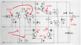
Module 2. You should be seeing around 0.7 volts across D1 + R8. Make absolutely sure you have the FET's in correctly (not reversed 😀) and that there is continuity from the FET pins to the correct points on the board.
You can't really test resistors in circuit and the wildly different readings between modules don't ring any alarm bells at this stage.
Running this module on -/+19 volts you should see around these voltages give or take. We know your output settles at Vcc. How do the other voltages compare ? We are looking for a huge discrepancy that would point to a fault semiconductor (or other problem).
Attachments
Could C3 be leaky? Even though you said you had replaced the electrolytics, try desoldering it and re-test on the board reading 1.3Mohms. If not C3, C7 may be suspect.A bit more checking and found a short on one module from the junction of tr1/tr2/r3 to ground. Now corrected.
With both boards fully disconnected and measuring resistance from pin4 to pin1 I get -14M on one board and +1.3M on the other. Theres a clue there I am sure 😉
MM
A bit more checking and found a short on one module from the junction of tr1/tr2/r3 to ground. Now corrected.
With both boards fully disconnected and measuring resistance from pin4 to pin1 I get -14M on one board and +1.3M on the other. Theres a clue there I am sure 😉
MM
Concentrate on one module at a time. The one with non adjustable current sounds like it could be OK... test it as I outlined 🙂 Lets get that one fully operational first.
(the slightest residual voltage across any resistor will totally confuse a DVM on resistance checks, as will the presence of semiconductor junctions... fault find by voltage measurement if possible)
OK - Light bulb tester made and one module tested.
This is 'red dot' module as I have marked it to avoid confusion!
+/- 44.5V supplied to module, 200mA A/S fuses OK.
24mV across speaker output and ground OK.
turning RV1 results in no current increase (previously it was at 1/4 turn), no reading on a 300mA scale.
Tr4 has 44V approx across it.
D1/R8 has 0.66V
MM
Just to let you know that both modules are now exhibiting the same behaviour (I guess that short circuit was the reason one was different).
Now both have around 25mV on the speaker output (good) but no current drawn when RV1 is increased (not good).
MM
Now both have around 25mV on the speaker output (good) but no current drawn when RV1 is increased (not good).
MM
- Status
- Not open for further replies.
- Home
- Amplifiers
- Solid State
- Maplin GA28F mosfet disaster - Can anyone help me out here?