Hello,
I'm building a valve preamp and have encountered some difficulties. Almost all of them are resolved, yet, I have a question which I believe is of the most importance. The preamp is meant to be a clean guitar preamp (external) that adds the "valvey" sound, without going to any sort of major distortion. It's supposed to be almost like a saturation pedal, a stompbox, thus having no intention to be directly connected to a power stage; instead, it'll be connected to the input of a solid state preamp and go throught it's preamp and power stage, or possibly throught the amp's fx loop.
SO, my problem: I believe outputing the signal only through a coupling cap will destory the amp by the voltage. So? What should I do? I tought of an audio transformer, but they don't become the best option when trying to keep this build at a low cost, so is there any other alternative (a reliable and decent sounding on)? And if I have absolutely have to go with transformers, what type should I use? I understand near to nothing about them 😕 .
Sorry for the long post 😀 and any help would be great,
Joo
You just attenuate the tube preamp output signal.
Don't know what schematic you used (post it here 😉 ) but a typical 12AX7 stage fed 250/300V can easily put out 60/90 V RMS 😱 ; you can attenuate it 20X with, say, a 220k resistor in series with a 10k audio pot.
220K is an "easy" load for the tube preamp , the 10k ouput impedance is fine for most SS power amps or effect loop in and the use of a potentiometer lets you a final adjustment on how much it puts out.
Win-win-win situation.
Ask a moderator to move this thread to the Musical Instruments section.
You just attenuate the tube preamp output signal.
Don't know what schematic you used (post it here 😉 ) but a typical 12AX7 stage fed 250/300V can easily put out 60/90 V RMS 😱 ; you can attenuate it 20X with, say, a 220k resistor in series with a 10k audio pot.
220K is an "easy" load for the tube preamp , the 10k ouput impedance is fine for most SS power amps or effect loop in and the use of a potentiometer lets you a final adjustment on how much it puts out.
Win-win-win situation.
Ask a moderator to move this thread to the Musical Instruments section.
Thank tou a lot dor the help.
I'm still learning the best I can on how tube preamps work and I'm now focused on the PSU for the plate. Once I get all the "prototype" schematics together and draw the
final, I'll post it here.
Thank tou once again.
 Moving to Instruments & Amps per forum policy. Likely you will get more answers there as well.
Hello,
....
SO, my problem: I believe outputing the signal only through a coupling cap will destory the amp by the voltage. So? What should I do?
A capacitor can't pass DC voltage. What EXACTLY are you worried about? Posting a schematic would help.
But a transformer would help especially if you are going to record or send the signal to a mixer. Both of those devices would like to have a balanced XLR output from your preamp. The transformer would have balanced output. But if going to a guitar amp a capacitor isolation would work fine. You will likely need a rather large cap. I'd need to see a schematic to know how large.
For decent quality matching transformers look at Edcor. You should be able to get what you want under $20. As so little power will go through the transformer.
Here is a 1:1 matching transformer that is likely larger than you need https://www.edcorusa.com/xsm15k-15k
But with no schematic I can't say if this is the one.
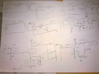
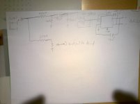
Hello again. Been looking at some design and came up with the almost-final version. I still have some doubts about mostly the power supply and, off course, the output stage. I want a output to the amp and a balanced output to connect directly to a desk or to a preamp. what do you think about this? Should use an op amp on the output to amp?
P.S.: Sorry about the bad quality schematics. Also, that unnamed rectangly IC is an DRV134
P.S.: Sorry about the bad quality schematics. Also, that unnamed rectangly IC is an DRV134
Attachments
Last edited:
Also, if I hadn't made myself clear, this is supposed to be something like a stompbox/peadal, to be driven almost clean just to add some colour to the sound. It's external to the amp itself and it's intended to be placed before an solid state combo just to had that warmness of the tubes to the sound. So the output of this preamp must me similar to the output of, for example, a boost or e.q. pedal, with a impedance and current safe to be fed into a amp's input.
Also, if I hadn't made myself clear, this is supposed to be something like a stompbox/peadal, to be driven almost clean just to add some colour to the sound. It's external to the amp itself and it's intended to be placed before an solid state combo just to had that warmness of the tubes to the sound. So the output of this preamp must me similar to the output of, for example, a boost or e.q. pedal, with a impedance and current safe to be fed into a amp's input.
In the first post you say you want a balanced output to drive a mixer or some recording gear then in the next post you say you want this to drive a guitar amp input witch is unbalanced.
If you want to be able to go both ways I think a transformer is the best way because the guitar amp will ground one side of the secondary and NOT make a ground connection to this preamp. No ground loops with a transformer.
I think that is the best argument for using a transformer: You have perfect galvanic isolation, no hum.
The power supply looks very complex for just driving one small tube. But if you are looking for the cleanest signal possible then you've got it. But really you don't need a regulated B+ your CLCL filter is very good especially when you figure the tube is only going to draw a few milliamps of current.
Thanks for the quick reply.
So what type of transformer do you recomend? I'd like to keep the price at a minimum but also it should be quite well insulated due to the small dimension enclosure while having other transformers inside.
Also, I don't know if you are deep into PSU designing but what would you recomend to protect the power supply from inrush current? I'm using quite small transformers, inductors and only 450v instead of 630v caps, so I'm a bit worried that it could ruin some of these parts.
Thanks again for the help.
Thanks again for the help.
Also, I don't know if you are deep into PSU designing but what would you recomend to protect the power supply from inrush current? I'm using quite small transformers, inductors and only 450v instead of 630v caps, so I'm a bit worried that it could ruin some of these parts.
Thanks again for the help.
Generaly a small transformer has a lot of DC resistance on the secondary so in-rush is not a problem. Then your first filter cap is small, like say 50f. in-rsh ins not a problem. Look at the power supply simulator at Duncan Amps and let it calculate this for you.
PSUD2
This simulator will plot current vs. time fore. I doubt in-rush will be a problem.
But if you do decide to use a thermister to limit in-rush try using it un the AC mains side of the transformer where there is more current.
As for a suitable audio transformer. They are easy to find. Perhaps this decor is what you want:
https://www.edcorusa.com/wsm10k-600
The 600 ohm out is about right for going to a mixer but they make a 5:1 version too. I think you can ignore the center taps
just some questions:
1st- isn't the primary resistance too low, assuming that the 12ax7 output is at about 37K output impedance??
2nd- won't the current out of the transformer actually be too high that ca ruin the amp that it's connected to??
Best regards
J.
just some questions:
1st- isn't the primary resistance too low, assuming that the 12ax7 output is at about 37K output impedance??
Best regards
J.
You might use their 5:1 transformer. That 5:1 turns ratio gives you a 25:1 impedance ratio. this means your 37K tubes will appear on the output as 37K/25 = 1.5K ohms This is a reasonable output. for driving an amplifier
Transformers don't really have an impedance. They have an "impedance ratio". Yes they have a recommended impedance and if you follow that recommendation you are assured of getting the full rated bandwidth at the full rated power.
The worst case current in the transformer this happens when you short the secondary leads is determined by Ohm's Law I= V/R where R is the DC resistance in the secondary windings. Let's say the you use the power transformer below. It is much bigger then you need but still a reasonable choice.
http://www.hammondmfg.com/pdf/EDB269BX.pdf
The output is about 300 volts and the DCR is about 170 ohms. A capacitor "looks" like a dead short, until it is fully charged. So lets look at "in-rush"
If the above transformer is shorted you get 300/170 = 1.8 amps. The transformer is rated at about .01 amps so you think it would catch in fire and explode. But what happens in that in about 10 or 20 milliseconds the first filter cap is fully charged which makes the rectifier diodes stop conducting and then the current in the secondary goes to near zero. The transformer is a rather massive hunk of metal and takes far longer then a few tens of milliseconds to get warm.
Later the tubes begin to conduct and will daw about 20 milliamps from the filter cap and the transformer will "back fill" that current into the filter cap. Of course this is done in "spikes" 120 times per second when the diodes switch on. but on average the transformers supplies about 20ma. It is rated at 100ma so we are OK.
2nd- won't the current out of the transformer actually be too high that ca ruin the amp that it's connected to??
As said, the current out of the PT is about 2A for a few AC cycles and then drops to match whatever the tubes draw. They are running in class-A so the current depends on how they are biased. But it will not be much, just a few ma.
As said, the current out of the PT is about 2A for a few AC cycles and then drops to match whatever the tubes draw. They are running in class-A so the current depends on how they are biased. But it will not be much, just a few ma.
Thanks. Yet, I think you misunderstood. In the first question I was refering to the Power Transformer, and also, I was planning on usig one much smaller than that ( the 229A230 Hammond Mfg. - Power Transformer - (229 Series) ) hence my worry. About the second question, I wals refering to the output transformer. Won't the current drawn peak in a way that can ruin the amp that is connected to it? Also, for the balancing do you support the use of an balancing IC like the DRV134 or to add another transformer?
Thanks once again for the help, really appreciatte it.
Thanks. Yet, I think you misunderstood. In the first question I was referring to the Power Transformer, and also, I was planning on usig one much smaller than that ( the 229A230 Hammond Mfg. - Power Transformer - (229 Series) ) hence my worry.
The current in the power transformer is determined by the load. In the first 20 milliseconds the load will look like a dead short. After that the load will be the bias current in the tubes. Use the power supply simulator at Duncan amps (linked to above) to get EXACT plots of current v. time. You will be fine.
The current is determined by the input impedance of the amplifier. In a guitar amp this is typically 1M The current will be well under 1ma even in the worst case. Believe me it is really hard to burn up a 1M resister.About the second question, I wals refering to the output transformer. Won't the current drawn peak in a way that can ruin the amp that is connected to it?
The mixer as used for recording or PA might have maybe as low as 20K input Even if your box puts out a 10 volt signal you are only at 0.5ma going to a 20K load.
Also, for the balancing do you support the use of an balancing IC like the DRV134 or to add another transformer?
Thanks once again for the help, really appreciatte it.
I like the transformer because it provides 100% galvanic isolation, not a chance of a ground loop. It is also very robust
BTW that very small Hammond PT you found looks good but you still need a 6.3 or 12.6 volt filament transformer for the tube heaters. The other larger PT I linked to has the heater secondary in the same transformer. It also comes with steel end bells that provide a lot of mechanical protection but is is large enough to power my small 5W practice amp.
One other thing I've done to power a tube based effects box is to literally crush to plastic power cubes a vice and salvage the internal transformers. I find two that take mains AC volts to 12VAC and wire the two 12VAC secondaries together. I use this for the hearers and the B+ voltage comes out at about 1.4 times the local AC mains volts.
I've simulated it and it says thenrush current at the transformer would be about 2,5A for just a few mseconds, but it doesn't include the polyswitches or any other protection that i may further implement. The signal seems to be quite steady and noise free, which I'm really about. For the heater I'm planning on using a similar transformeralso from 229 series, but with the output at 12VDC. I'd really like to use that transformer you showed, but sadly it doesn't fit inside the enclosures i'm planning on using, and also since I live in europe I need the primarys to be 230V. Thanks alot for your help so far, it's been great. Now it's just the final little tweaks and I think I0m ready to build it. Just one last (or one of the last) questions: how cheap do you believe I can go with a DI transformer without risking serious losses in audio quality?
Best regards,
J.Dias
Best regards,
J.Dias
Last edited:
. how cheap do you believe I can go with a DI transformer without risking serious losses in audio quality?...
High quality audio transformers are usually spec'd for 20Hz to 20KHz. But a guitar with standard tuning (Low E on largest open string) the lowest sound it can make is 80Hz. This means a guitar transformer can have 1/4 the amount if iron core material or looking at this the other way, most audio transformers are grossly over built for use with guitars. I have been buying low power audi matching transformers on eBay and I can normally find them for $10 or less. Yes some are sold are very high prices but if you hunt and wait.
The last one was a microphone input transformer spec'd 150:15K kms -1dB that was innside a mu-metal can for $8. The can is about 1 inch diameter and 1 inch long. A new one sells for about $100 from Jenson. edcor.com makes good ones but not metal cans for maybe $12.
One more thing. Look here: High performance audio transformers and ground isolators.
Click on the "resources" tab and read EVERYTHING including app notes, schematics and so on. They will make you log-in before you can read this but it's free and worth the effort. This is one of the world's premier audio transformer companies. They have very detailed answers to everything you have asked, much better than I can write. If you need schematics for a transformer based opamp or tube circuit that have it. Also some white papers on ground loops, inpedence machines and so on. But their prices are very high
Tiny transformers for mic inputs will saturate, especially if they have any DC current through them, as in a typical output circuit. Hammond has a line of $20-ish line transformers that will do the job just fine. I use this series for DI outputs from amps I've built. As has been said, you don't need wide frequency response in this MI application. Normally, I use a cathode follower to drive the transformer and a resistive pad to match levels and impedance.
Last edited:
Tiny transformers for mic inputs will saturate, especially if they have any DC current through them, as in a typical output circuit. Hammond has a line of $20-ish line transformers that will do the job just fine. ....
Yes they will saturate. No doubt. I recommended the Jenson web site as a source of good technical information, not as a source of transformers.
Encore makes some decent matching transformers too. Hammond always is the conservative choice.
- Status
- Not open for further replies.
- Home
- Live Sound
- Instruments and Amps
- Preamp Output Transformer