http://glass-ware.com/User_Guides/PS-3.pdf
The PS-3 is one of the more complete correct guides that I have seen. You can use CT or non CT and the circuit is simple to follow.
I have a modified one using a CT xformer giving over 500V B+ for a push pull amp and it works great. Using the DC for front end heater voltage and using a separate winding for AC on the power tube heaters. The amp is dead silent.
I'm one step away from ordering the PS-3, but since my goal was to have this completed by Nov 15, and it's now much later... I'm considering another attempt at the power supply. It may be that my transformer of 5A 12.6V provides 2x the current - which may be why I smoked a cap on the Aikido board when I had it hooked up.
If I found something that draws 2.5A - lightbulbs and led's to get to the 31.x watts at 12VDC and put that before the power supply and transformer... this is getting ridiculous - but would that work?
If I found something that draws 2.5A - lightbulbs and led's to get to the 31.x watts at 12VDC and put that before the power supply and transformer... this is getting ridiculous - but would that work?
just because it is capable of 5A doesnt mean that is what is going through the circuit.
Caps blow when their voltage is exceeded.
Your xformer for the heaters just has some headroom thats all.
You have to follow the flow of electricity. Burning resistors typically mean you have a short somewhere...or something is drawing so much current that it exceeds the wattage rating.
Caps blow when their voltage is exceeded.
Your xformer for the heaters just has some headroom thats all.
You have to follow the flow of electricity. Burning resistors typically mean you have a short somewhere...or something is drawing so much current that it exceeds the wattage rating.
On the PS-14 -That would have been R1, a flash and pop with black smoke. I had a bad connection on R7 - I was tired of the rework, removing solder so I used just enough to hold it in place. When I mentioned it to an amp repair person he suggested checking the diodes as well. It was producing 12.58V before I blew R1 and after I replaced only R1. I don't doubt for a long term solution I would replace C1-4, D1-4 and R1-4.
In the manual it states a 12.3V 2.5A transformer could be used, where I have one that is providing 5A. I was assuming that simply because current was available, it was not used. Like I plug a lightbulb into a 30A circuit, it doesn't draw 30A.
It was C18 on the Aikido board which presumably made the white smoke. I turned off the power, pulled the plug and left the room for the evening for the fumes to dissipate. The cap was a bit bulged. The amp repairman that I asked to sell me another 18V panasonic 3300uf capacitor - he pointed out it was not a FM as the bag and instructions stated. All he had were 3300uf in I think 50V which he said would be fine - and they were FM.
Last edited:
Burning resistors typically mean you have a short somewhere...or something is drawing so much current that it exceeds the wattage rating.
I could have been sloppy with the R7 and had a short for the PS-14 pop, but it should have been good when I hooked it up to the Aikido.
The tubes I'm using for initial testing are dirt cheap ebay Russian 6H... something which are supposed to be equivalent to 6SN7 - so maybe they are way out of spec.
I should mention I only tested the heater voltage when it was not hooked to the Aikido board - so no load. It is now attached to the board, I've replaced the capacitor that make white smoke.
Just now I tested AC from the transformer and noticed a 12.8 ish reading and quickly moved on to switch to DC, but by the time I had the leads on the pads the next C18 opened up and sprayed.
C18 was oriented correctly.
insert random words of ....
here are the tubes I'm starting with. don't have a way to test how much current they are drawing when the cap blows up before I can get the meter test leads on.
http://www.ebay.com/itm/191250981827?_trksid=p2059210.m2749.l2649&ssPageName=STRK:MEBIDX:IT
Last edited:
now with pics
I'm not sure what the issue is but when I went to apply heater voltage C18 on the Aikido board blows within 45 seconds. The first cap that came with the kit was 18V 3300uf. The second cap was picked up locally, rated at 50V 3300uf and only lasted about 20 seconds before venting.
I have not applied B+ voltage to the board.
As mentioned I am using 6SN7 equivalents. (so far as I trust the seller and what I've found online).
The heater voltage transformer is 12.6VAC, a Hammond 166N12 which can provide 5A. The manual for the PS-14 states using 2.5A and don't suspect it is critical that there is reserve current available. Maybe I am wrong.
Heater is configured (or I think it is!) as a full wave bridge. The center tap from the transformer is not used.
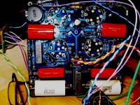
Ground is a piece of heavy wire for this test build. The wooden box is just to hold pieces in place until I decide on a final design and have metals cut. Aluminum, stainless and carbon steels with some copper in the final design - but that's not the topic at this point.
Why am I blowing C18 on the board?
I am reading damn close to 12.6VDC on the output.
The jumpers on the Aikido board are J2 & J5.
Here is what is out of spec from the PS-14 manual. The capacitors C7 through C10 provided are 0.1uf, where the manual and label on the bag for those capacitors states 0.01uf. I'm getting the voltage I expect - so is it crucial? I have both values on hand currently so they could be replaced.
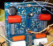
Yes, in the photo's there are resistors on the bottom of the board. The values were backwards in both instructions and labels. Maybe the common mistakes made up for each other but I had to switch them a couple of times.


I'm not sure what the issue is but when I went to apply heater voltage C18 on the Aikido board blows within 45 seconds. The first cap that came with the kit was 18V 3300uf. The second cap was picked up locally, rated at 50V 3300uf and only lasted about 20 seconds before venting.
I have not applied B+ voltage to the board.
As mentioned I am using 6SN7 equivalents. (so far as I trust the seller and what I've found online).
The heater voltage transformer is 12.6VAC, a Hammond 166N12 which can provide 5A. The manual for the PS-14 states using 2.5A and don't suspect it is critical that there is reserve current available. Maybe I am wrong.
Heater is configured (or I think it is!) as a full wave bridge. The center tap from the transformer is not used.
Ground is a piece of heavy wire for this test build. The wooden box is just to hold pieces in place until I decide on a final design and have metals cut. Aluminum, stainless and carbon steels with some copper in the final design - but that's not the topic at this point.
Why am I blowing C18 on the board?
I am reading damn close to 12.6VDC on the output.
The jumpers on the Aikido board are J2 & J5.
Here is what is out of spec from the PS-14 manual. The capacitors C7 through C10 provided are 0.1uf, where the manual and label on the bag for those capacitors states 0.01uf. I'm getting the voltage I expect - so is it crucial? I have both values on hand currently so they could be replaced.
Yes, in the photo's there are resistors on the bottom of the board. The values were backwards in both instructions and labels. Maybe the common mistakes made up for each other but I had to switch them a couple of times.
The B+ wires were from pads for those building dual mono, I twisted them to make them more rigid and brought them to the same solder pad on the stereo board. ... but I haven't even finished the heater problem... if B+ will be an issue will deal with it once I have the current problem solved.
 the last one will be messy to reduce the flash...


Attachments

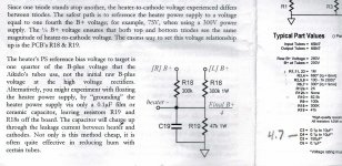
Another thought is on the voltage divider for referencing heaters to B+/4. Usually 300k on top and 50-100k on the bottom.
This may have to do with my coffee not working yet and not having a shower to wake up - or the same for my multimeters - but I'm getting weird values at those resistors.
I did touch the capacitors with a resistor briefly to be sure they were drained but haven't done the "short them with a screwdriver".
Specifically those for referencing B+, R18 are not giving a reading but wandering all over the place. I need to make some alligator clip leads - I haven't applied any B+ voltage - unless the 12.58V from ground is able to enter the circuit. After leaving probes resting one settled at 149.5 where it is a 300K resistor. Maybe they are in parallel.
Would love a real, searchable copy of the current PDF for both products. I have a full version of Acrobat Pro, but don't really use it. Versions which come up in searches and appear on Broski's site are good, but the off site copies usually are not searchable.
Aikido octal blowing cap without B+ applied
From the PS-14 I have not been able to calculate the value of R7 to drop B+. There are pictures of the boards a few posts back. Pictures that might help people see if there are obvious mistakes.
The real issue is with heater voltage applied, a capacitor on the Aikido board blows.
Heater is 12.58VDC.
B+ is 348, higher than ideal (but has NEVER been applied to the Aikido board). I originally had a 1.6K resistor in place but now a 3K. I can't measure it under load because the capacitor C18 blows on the Aikido board. It came with a 16V 3300uf which I smoked, and then smoked a 50V 3300uf purchased locally.
I'm planning on running 6SN7's. The values I have installed are on the column on the right. Am I anywhere near the 1/4 ratio? Doesn't appear that way to me. Have I tried the removal of R18 and R19 and floating the heater? No, does anyone else have to go through that trouble? I wouldn't know where to begin. Is it assumed one leaves C18 and C19 off the board as well?

I have never applied B+ to Aikido. Never turned the transformer for B+ on while the heaters were on, and never applied it when the heaters were off.
I was going to, but it went poof before I could test what heater voltage / current was at tubes.
So if what we are trying to rule out is reference between heaters and B+ :
C19 has this value -WFD2W104 - it is rated at 450VDC, with failure at 450VDC x 150 for 60 seconds. The first item on the page linked below.
http://industrial.panasonic.com/ww/i_e/21088/drawing_wfd_e/drawing_wfd_e/wfd2w_b_q_e.pdf
I have discharged C19 the best I can, even shorted it when done (OK, by now I have drained then shorted all capacitors), but not removed it. Meters are very slow to get a reading on R19 - it starts about 30K, then over the course of a couple of minutes will climb close to the 47K it is supposed to be rated according to build instructions. I need to build the banana clip leads because I can’t stand there holding them still long enough to confirm.
R18s, which are close in proximity to the blowing C18 are reading 150 instead of 300, but perhaps that is because there are two in parallel - orange, black, yellow, gold - 300Kohm - They too are slow to read, it takes a couple of minutes to climb to 150.
I can probably find a .1uf 1kV to beef up c19 locally. Don't know if it will make a difference. Certainly I'm not the first person to apply heater voltage only for more than 30 seconds before turning on the B+ transformer.
I don’t know what position the coupling cap selector switch is in currently or if it matters at this point.
I have a strong aversion to removing the wires as it was a royal pain to get them back in. I used 18g wire. I could ream the holes on the board a little, but worried I would tear a solder pad off.
I do not have a signal ground connected at this point, and don’t have any signal going into the circuit. While many signal wires are connected (without a pot or attenuator at this point), there is no signal to ground and haven’t decided which points should go to ground or if I can get away with only a pair of signal to ground connections. I haven’t thought it through.
From the PS-14 I have not been able to calculate the value of R7 to drop B+. There are pictures of the boards a few posts back. Pictures that might help people see if there are obvious mistakes.
The real issue is with heater voltage applied, a capacitor on the Aikido board blows.
Heater is 12.58VDC.
B+ is 348, higher than ideal (but has NEVER been applied to the Aikido board). I originally had a 1.6K resistor in place but now a 3K. I can't measure it under load because the capacitor C18 blows on the Aikido board. It came with a 16V 3300uf which I smoked, and then smoked a 50V 3300uf purchased locally.
I'm planning on running 6SN7's. The values I have installed are on the column on the right. Am I anywhere near the 1/4 ratio? Doesn't appear that way to me. Have I tried the removal of R18 and R19 and floating the heater? No, does anyone else have to go through that trouble? I wouldn't know where to begin. Is it assumed one leaves C18 and C19 off the board as well?
I have never applied B+ to Aikido. Never turned the transformer for B+ on while the heaters were on, and never applied it when the heaters were off.
I was going to, but it went poof before I could test what heater voltage / current was at tubes.
So if what we are trying to rule out is reference between heaters and B+ :
C19 has this value -WFD2W104 - it is rated at 450VDC, with failure at 450VDC x 150 for 60 seconds. The first item on the page linked below.
http://industrial.panasonic.com/ww/i_e/21088/drawing_wfd_e/drawing_wfd_e/wfd2w_b_q_e.pdf
I have discharged C19 the best I can, even shorted it when done (OK, by now I have drained then shorted all capacitors), but not removed it. Meters are very slow to get a reading on R19 - it starts about 30K, then over the course of a couple of minutes will climb close to the 47K it is supposed to be rated according to build instructions. I need to build the banana clip leads because I can’t stand there holding them still long enough to confirm.
R18s, which are close in proximity to the blowing C18 are reading 150 instead of 300, but perhaps that is because there are two in parallel - orange, black, yellow, gold - 300Kohm - They too are slow to read, it takes a couple of minutes to climb to 150.
I can probably find a .1uf 1kV to beef up c19 locally. Don't know if it will make a difference. Certainly I'm not the first person to apply heater voltage only for more than 30 seconds before turning on the B+ transformer.
I don’t know what position the coupling cap selector switch is in currently or if it matters at this point.
I have a strong aversion to removing the wires as it was a royal pain to get them back in. I used 18g wire. I could ream the holes on the board a little, but worried I would tear a solder pad off.
I do not have a signal ground connected at this point, and don’t have any signal going into the circuit. While many signal wires are connected (without a pot or attenuator at this point), there is no signal to ground and haven’t decided which points should go to ground or if I can get away with only a pair of signal to ground connections. I haven’t thought it through.
Attachments
Last edited:
I didn't blow c18 for a change.
I threw the Hammond 12.6VAC 5A transformer out of the equation and went with one pair (blue / green) of the secondary windings of 6.3VAC. I also threw the switch out.
For now the other two are tied up.
A few jumper changes and...
Tubes glow from heaters but I haven't determined what they are drawing. We can guess the 10mA each?
I'm getting 258VDC which is more of a drop than I expected.
For those that know the math, and are not making random guesses like I am - what effect would adding the second pair of windings have?
How is the 3K resistor at R7 on the power supply going to work as far as ripple - it got me a lot closer than I expected, or even wanted but I'll take it.
I threw the Hammond 12.6VAC 5A transformer out of the equation and went with one pair (blue / green) of the secondary windings of 6.3VAC. I also threw the switch out.
Good call. Very good call.
A few jumper changes and...
To verify, you changed the jumpers to 6.3V on the Aikido board or changed to a voltage doubler circuit on the PS-14?
Tubes glow from heaters but I haven't determined what they are drawing. We can guess the 10mA each?
6SN7 has a standard heater draw of 600mA (0.6A)
I'm getting 258VDC which is more of a drop than I expected.
For now, don't worry about it
For those that know the math, and are not making random guesses like I am - what effect would adding the second pair of windings have?
Second pair of what windings?
How is the 3K resistor at R7 on the power supply going to work as far as ripple - it got me a lot closer than I expected, or even wanted but I'll take it.
Closer to what?
As for ripple, essentially any R in a CRC filter is beneficial.
changed the jumpers on the Aikido board.
as to which second pair of windings, there is another pair of windings off the Antek. The manual says there are two green two blue, but there are one green, one blue, one brown, one orange. i ran across some wiring color chart that suggested those could be different current colors but never tested.
closer to what - closer to the B+ voltage that's within range.
for now i want to get it working, and if i want to break it in the future in the name of improvement then i'll remember the last few weeks of special headaches then.
admit i am doing a sloppy job of signal wiring and will need to redo it but there isn't time before christmas to get the metal cut for the chassis. dang it if i'm not doing everything i can to get so i can listen to at least one album before going to visit family for the holidays.
dang it if i'm not doing everything i can to get so i can listen to at least one album before going to visit family for the holidays.
Rushing a tube project is a great way to get high-voltage shocks. Ya might want to reconsider your deadline.
yes, will wait for review of complete circuit.
done for the evening other than drawing out - and i know i don't have signal ground done.
done for the evening other than drawing out - and i know i don't have signal ground done.
Yank out C18 and observe voltage on the pads and then each one with respect to earth ground. Or asked another way take readings at h+/h-
With the divider in place you should get b+/4 with respect to ground at each pad with the difference being the voltage you set at the output of the regulator.
There is also no reason not to send b+ to the aikido board
With the divider in place you should get b+/4 with respect to ground at each pad with the difference being the voltage you set at the output of the regulator.
There is also no reason not to send b+ to the aikido board
- Status
- Not open for further replies.
- Home
- Amplifiers
- Tubes / Valves
- Aikido starter help requested