Did you mean simulation driven? 🙂 Anyway I thought it was an accepted fact that a CRC pi filter gives more attenuation than a single capacitor of the same total capacitance.
No, I mean data driven. I just happen to see more of the complete picture than most. CRC circuits were/are common in tube supplies, where attenuation is what you want. Tube circuits draw relatively low currents, hence, can tolerate a higher output impedance in the power supply than semiconductor amps. In the case of a tube amp, a good design choices would be to trade off output impedance in exchange for ripple attenuation.
In a semiconductor amp, which draws amps of current, what you want is low output impedance in the supply. Recall that even with a regulated supply, there is ripple present at the power connector to the amplifier resulting from the I*Zout drop across the output impedance of the power supply and cabling. With a regular, unregulated supply, this I*Zout term is in addition to the ripple voltage present across the reservoir caps.
Hence, in a semiconductor amp, the name of the game is low output impedance. To get low ripple voltage, increase the supply capacitance. At the low voltages that semiconductor amps operate at, this is easy. Just buy a bigger can...
Well, if you're going to the trouble of making another board then yes, the only issue becomes the real estate.
As I said earlier, it's not just real estate. It's real estate = money, documentation, testing, support, etc.
In this case, kludging the components under a separate board makes less sense than providing the option. As already has been stated, the amp has SOTA PSRR that makes the need for a quiet supply irrelevant but his clients are likely to be people who would whine about this kind of thing so even though it makes no engineering sense, I suppose Mark's point wins.
My customers range in skill level from people who have never built an electronics kit to well-educated and experienced electrical engineers. The former group needs something that will work well out of the box. The latter crowd does also, but has the skills to modify as they see fit.
I agree that this Snubbergate (to borrow a much overused term) is mostly a perception issue. My supply board may be perceived as less SOTA because it does not include an RC snubber. I'm willing to take that risk. I'm willing to take the risk because I have data to show that the RC snubber makes no difference in the performance of the Modulus-86.
In the Modulus-86, I've actually taken on quite a bit of "perception risk" already. For example, I use elaborate planes and pours (including split ground planes) to get to the SOTA performance level. I was concerned that the use of planes would cause the Giant Spider Star Ground Crowd to get upset. I could have used a Giant Spider Star Ground as well, but it would have been impossible to get SOTA performance that way. Specifically, the THD above 1 kHz would have been degraded by several orders of magnitude. You can find the data in the LM3886 P2P vs PCB thread.
I base my decisions on engineering. If something is a problem, I'm going to address it. However, if something is NOT a problem, I won't require my customers to spend the time or money addressing it.
The supply board will be out of the fab next week.
~Tom
Last edited:
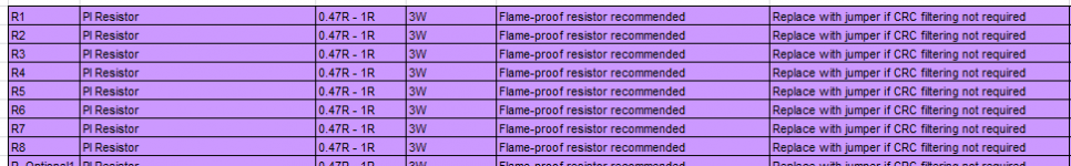
Whoops, you have forgotten that this is intended to be a Universal Power Supply board. Some customers really do want the CRC filter, and this board enables them to have what they want. Other customers certainly do NOT want the CRC filter, and they can have it their way too! Simply replace R1-R8 by jumper wires. In fact the Bill Of Materials even says so (attached).The DIYA Universal Supply Board may include fancy snubbers, but then designers turn around and throw away the benefits of the first supply cap by implementing CRC filtering. It takes five minutes in SPICE to work out that you'll get the best filtering by having the two caps in parallel, or even better by having a bigger cap. Yes, that's contrary to the common DIY belief as well.
I think the designers of this PCB were a lot more shrewd than you give them credit for. They aimed at a certain target, and hit the bullseye, in my opinion.
_
Attachments
No, I mean data driven. I just happen to see more of the complete picture than most... Hence, in a semiconductor amp, the name of the game is low output impedance.
I think I see what you are saying. Basically you are assuming the power amp to have good enough PSRR that it won't be bothered by whatever noise and ripple can make its way through a single section RC, so you might as well have all the capacitance in one place for lower output impedance and higher current delivery?
I guess that is valid. I've certainly always had perfectly good performance from SS power amps using the ordinary single section power supply filter. But I guess I can see the other point of view in this thread, a "Universal" power supply board should cater for exotic designs with lousy PSRR. 🙂
It is also wrong to describe the single section as the "best filtering" when it is really worse filtering but better energy storage.
I guess you thought the distortion performance of the regular LM3886 circuit was a problem then. I can't think of any engineering justification for reducing it by another 2 orders of magnitude when it was already satisfactory. (Disclaimer: I still like the project and am tempted to build it)I base my decisions on engineering. If something is a problem, I'm going to address it.
Last edited:
I guess you thought the distortion performance of the regular LM3886 circuit was a problem then. I can't think of any engineering justification for reducing it by another 2 orders of magnitude when it was already satisfactory. (Disclaimer: I still like the project and am tempted to build it)
But of course if the goal is 'reducing distortion of LM3886 to below noise floor with available test kit' and the enhanced snubber makes no difference to the measurement then Tom is totally valid is his view. If it did he would have included it.
The fact that there is a universal board available for people who feel snubbing is important, along with a documented technique for how to optimise just gives choice. Choice is good. My view is that, once you accept that bias drives perception (even if your bias is that, if it is well engineered then you cannot make it sound better) then you can forgive people for going beyond the point where it logically can't make a difference.
Also using Spice, many years ago when I did my own version of a gainclone, and including realistic transformer and rectifier parameters, it was clear that there were real world benefits to the CRC arrangement in the simulation. Hence my assembled unit used such, and I had no issues with PS inadequacies, just using a straight LM38xx part for amplification duties.In a semiconductor amp, which draws amps of current, what you want is low output impedance in the supply. Recall that even with a regulated supply, there is ripple present at the power connector to the amplifier resulting from the I*Zout drop across the output impedance of the power supply and cabling. With a regular, unregulated supply, this I*Zout term is in addition to the ripple voltage present across the reservoir caps.
Hence, in a semiconductor amp, the name of the game is low output impedance. To get low ripple voltage, increase the supply capacitance. At the low voltages that semiconductor amps operate at, this is easy. Just buy a bigger can...
Also using Spice, many years ago when I did my own version of a gainclone, and including realistic transformer and rectifier parameters, it was clear that there were real world benefits to the CRC arrangement in the simulation. Hence my assembled unit used such, and I had no issues with PS inadequacies, just using a straight LM38xx part for amplification duties.
So a straight 3886 amp benefits from CRC, whereas a pretty well optimised Composite doesn't. Who'da thunk it.
Not quite ... I was responding to Tom's comment that
I found otherwise - I got a better performing supply for the same overall C, using CRC strategies. Which will benefit amplifiers composite, and straight ...
It takes five minutes in SPICE to work out that you'll get the best filtering by having the two caps in parallel, or even better by having a bigger cap.
I found otherwise - I got a better performing supply for the same overall C, using CRC strategies. Which will benefit amplifiers composite, and straight ...
Better performing according to which parameters? Tom Has stated that he is optimising for ripple voltage.
Which ripple voltage?
That coming from the mains or that due to load changing?
These two ripples require different solutions to achieve acceptable attenuation.
That coming from the mains or that due to load changing?
These two ripples require different solutions to achieve acceptable attenuation.
As Andrew asked, which ripple? I was looking at the worse case scenario, when a load was demanding high current from the mains - so what I was aiming for was the best ripple/sag solution, that placed the least stress on the rejection capabilities of the circuit.
Here we go again. We're done with Snubbergate. Now it's Filtergate. Great...
Regardless of what supply filtering you use, the Modulus-86 performs as well on a regulated lab supply as it does on a simple supply consisting of a toroid, rectifier, and two filter caps (22000 uF each). I see no reason to make it any more complicated than that. I designed an amplifier with stellar supply rejection for a reason, ya know.
For those interested in engaging with Andrew the filter discussion, would you kindly start a thread in the power supply forum? That way the SNR of this thread can get back to a more reasonable value.
Thanks,
~Tom
Don't forget P2Pgate, GNDgate, Feedbackgate, PSUgate and Zobelgate, each contributing to an improvement of the initial design.
Modulus-86 gain: +20 dB (10x); change to +17 dB (7x),+14 dB (5x), +26 dB (20x), ...
I literally couldn't stand it anymore (I had to sit!), and ordered myself a Christmas present! 😉
Looking more closely at your site, you mention:
The Modulus-86 has a gain of +20 dB (10x). This value was chosen to ensure a good gain structure in the end application. Should a higher gain be needed, it can easily be modified for +26 dB at a minimal reduction in performance. Should a lower gain be desired for further optimization of the system gain structure, the Modulus-86 circuit supports the use of the THAT1203 and THAT1206 for a total amplifier gain of +17 dB (7x) and +14 dB (5x), respectively.
I probably missed it, but is that for balanced? What is it for single ended? 😱
As someone with many High Efficiency (HE) speakers and new to apartment living, my volume knob seldom goes past 9 o'clock !?!
2Vrms x 26dB(20x) = 40Vrms 😱 Even my Pass Pearl and simple JFET phonos output a strong signal ...
I'm always looking for more reasonable gain and love your 20db(10x) default 😀 [instead of that anachronistic 26dB(20x)]! 😡
So, how do you change Modulus-86 gain?
1) Swapping THAT1200 20dB(10x) to THAT1203 17dB(7x) or THAT1206 14dB(5x)
2) Going from +20 dB (10x) to +26 dB (20x)? Do you have a graph of the slight performance difference you mention? (I'm especially interested in 1W given my various HE speakers)
3) other gains?
Does it affect the sound at all?
Thanks for the great work,
Cheers,
Jeff
Last edited:
Don't forget P2Pgate, GNDgate, Feedbackgate, PSUgate and Zobelgate, each contributing to an improvement of the initial design.
This is one of those times I wish DIY Audio had a "like" button... 🙂
I'm not sure the heated discussion contributed to the design, but my experiments on grounding and feedback, simulations of the Thiele, Zobel networks, and, more recently, thermal experiments have certainly contributed. The discussions also led me to type up my Taming the LM3886 site which is rather popular.
I like the discussions, but they are often better served in separate threads to keep the SNR of each thread reasonable.
The Modulus-86 has a gain of +20 dB (10x). This value was chosen to ensure a good gain structure in the end application. Should a higher gain be needed, it can easily be modified for +26 dB at a minimal reduction in performance. Should a lower gain be desired for further optimization of the system gain structure, the Modulus-86 circuit supports the use of the THAT1203 and THAT1206 for a total amplifier gain of +17 dB (7x) and +14 dB (5x), respectively.
I probably missed it, but is that for balanced? What is it for single ended? 😱
The gain of the Modulus-86 is the same for differential as it is for single-ended.
As someone with many High Efficiency (HE) speakers and new to apartment living, my volume knob seldom goes past 9 o'clock !?!
I'm always looking for more reasonable gain and love your 20db(10x) default 😀 [instead of that anachronistic 26dB(20x)]! 😡
The volume control on my preamp reads out in dB, so I know exactly what the gain of my system is. My main amp has a gain of about 10 dB (3x). With my 87 dB/W*m efficient speakers, I rarely have the volume control past 0 dB and that only happens when I really crank it. Most of the time, the preamp sits at -30 dB or so.
The "standard" 26 dB THX gain is not optimal for home audio, but I guess they had to go with something.
So, how do you change Modulus-86 gain?
1) Swapping THAT1200 20dB(10x) to THAT1203 17dB(7x) or THAT1206 14dB(5x)
Yep. To lower the gain, you swap out the THAT. There are a few protection diodes that change as well. This is described in the Design Documentation, which you will receive in your email shortly.
2) Going from +20 dB (10x) to +26 dB (20x)? Do you have a graph of the slight performance difference you mention? (I'm especially interested in 1W given my various HE speakers)
Increasing the gain would require a resistor change in the feedback divider. I haven't quantified the performance degradation that you'll get by increasing the gain. The performance scales with the loop gain. For every increase of 6 dB in the closed loop gain, the loop gain decreases by 6 dB, hence, the THD, PSRR, and likely other performance parameters as well, degrade by 6 dB.
Does it affect the sound at all?
With high-efficiency speakers, you may get an improvement in the sound quality by decreasing the gain. This is because any noise coming from the source will be amplified less. Increasing the gain will have the opposite effect.
The only reason for increasing the gain is if your preamp/source cannot drive the power amp to produce enough SPL from the speakers.
Thanks for the great work
You're quite welcome.
~Tom
Tom,
I enjoyed reading your website. I have put DG300B on my to do list, but I'll need different speakers for those. Actually the speakers I just sold would be perfect... ain't that always how it goes?
My current project is 3way active speakers. I'm looking at your Modulus86 or the TP Sympatico for the amps. Sympatico is also a composite amp, using the 4780 bridged for 100wpc.
You said that Modulus-86 is the best semiconductor amplifier that you have ever designed. Does that include discreet and class A, too?
I'm sure 35wpc is enough for my tweeters and mids, but maybe not enough for my bass drivers with electronic boost. The voltage is probably enough, so if I just want more current can the amp just be paralleled without being bridged also?
Do you ever find the LM4562 opamp to sound closed in, spatially challenged, Brystonesque? It usually sounds like that to me. It does have great bass and very solid and palpable midrange, but not the best for "ambience." I am asking this because you say that the amp sounds like the opamp, and yet you also say that the amp sounds open and natural. Have you found a way to make the opamp sound more "open" than it normally does, just as you have found a way to make 3886 sound better than it normally does?
Thanks
Rich
I enjoyed reading your website.
Thank you. I appreciate it.
You said that Modulus-86 is the best semiconductor amplifier that you have ever designed. Does that include discreet and class A, too?
Yes it does.
I'm sure 35wpc is enough for my tweeters and mids, but maybe not enough for my bass drivers with electronic boost. The voltage is probably enough, so if I just want more current can the amp just be paralleled without being bridged also?
I suspect 35 W is enough, even for the woofer in a dipole setup with electronic boost. Recall, with a 3-way, you're only amplifying the bottom 1-2 kHz of the audio spectrum for the woofer.
Should you want more power, you can use a 4 Ω woofer. You can also bridge two Modulus-86 amps.
You can use the Modulus-86 by itself, two boards bridged, two boards in parallel, or four boards in a bridge-parallel configuration. If you plan to drive a 4 Ω load using a bridged amp, I strongly recommend using four boards in a bridge-parallel combination. For an 8 Ω load, you can get away with two boards in a bridge configuration. This goes for any LM3886-based amp, actually.
Do you ever find the LM4562 opamp to sound closed in, spatially challenged, Brystonesque?
Not really... But then I haven't spent a whole lot of time listening to just the opamp by itself. I use the LME49720 in my preamp. It sounds great when driving my DG300B or Modulus-86. The LME49720 (= LM4562) does not add anything to the source material, which may be perceived as "something is missing". I generally prefer that I like the presentation of the LME49720 over other opamps, though. Maybe I just know how to get the most out of the LME49720... 😉
~Tom
Thanks for the quick and thorough response, Tom.
My woofers are 8 ohm, 91dB drivers, in sealed boxes Qtc.5, crossing 2nd order @150Hz. I only need about 3dB of boost for baffle step, and my listening peak is ~100dB max, so maybe one module will work. Good to know there are options.
What size trafo to power 3 modules?
Your preamp must be balanced output?
Sizing a trafo sort of depends on your speaker load. 200VA is enough for a stereo pair in most circumstances (yours included) but if you're going to run the three modules individually from the same trafo, I would go no higher than 300VA. I like a little sag.
My woofers are 8 ohm, 91dB drivers, in sealed boxes Qtc.5, crossing 2nd order @150Hz. I only need about 3dB of boost for baffle step, and my listening peak is ~100dB max, so maybe one module will work. Good to know there are options.
In that case, you need about 10 W per channel. Designing for 30 W would give you 10 dB of margin.
What size trafo to power 3 modules?
I would plan for about 60~100 VA per board for 4 Ω operation on ±28 V rails. Less for 8 Ω operation. That's the short answer. The long answer can be found on my Taming the LM3886 : Power Supply Design web site. Note the Excel spread sheet "calculator" near the bottom of the page.
Your preamp must be balanced output?
You don't have to use a differential output. You get the best performance with a differential output, however, you will get very good performance even with a pseudo-differential connection to a single-ended source. You can see the difference in performance in Post #384. The cable needed for the pseudo-differential connection is shown below.
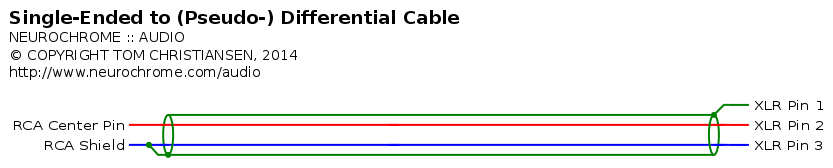
It's easy to make by lobbing off the male end of an XLR patch cord and soldering on an RCA connector. You can also find RCA-XLR cables ready-made.
~Tom
All drivers are 8 ohms, so I think I'm fine with 3 modules. Like you said I can always add more.
I'll read the Taming 3886 article again about sizing trafo. Thanks!
Will one of your upcoming PS boards power 3-4 modules, or is it designed to be one PS board per module? Is it a simple unregulated PS like that used with your test sample?
Thanks for answering my many questions!
Rich
I'll read the Taming 3886 article again about sizing trafo. Thanks!
Will one of your upcoming PS boards power 3-4 modules, or is it designed to be one PS board per module? Is it a simple unregulated PS like that used with your test sample?
Thanks for answering my many questions!
Rich
- Home
- Vendor's Bazaar
- Modulus-86: Composite amplifier achieving <0.0004 % THD+N.