After long time being inactive in diyaudio forum (take some rest after surgery) i have to finish my build for dcb1. I'm very curious with the sound.
This week i finished the pcb. Thanks to Mr. Salas, last time i got guidance directly from you about drawing the pcb for my self. I have some pict, i will upload later. Now time to populate the components
This week i finished the pcb. Thanks to Mr. Salas, last time i got guidance directly from you about drawing the pcb for my self. I have some pict, i will upload later. Now time to populate the components
Thanks Stixx
my board almost finished. here it is :
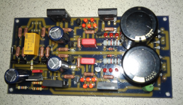
I forget to buy BC550 and BC517.. I have some BC547. I think it can be used to replace BC550, but I dont have any idea with other transistor to replace BC517.
I have to go to bed now... still feel some pain..need some rest.
I'm happy with my board progress. wish I could finish it in my dream heheheh
my board almost finished. here it is :
I forget to buy BC550 and BC517.. I have some BC547. I think it can be used to replace BC550, but I dont have any idea with other transistor to replace BC517.
I have to go to bed now... still feel some pain..need some rest.
I'm happy with my board progress. wish I could finish it in my dream heheheh
Looks nice. Maybe BC547 has no problem driving your relay, its a different type, so try. In case you will experience mechanical noise from the relay, just put 100nF capacitor between C-B pins of the BC547 the one connected to the relay coil.
I never use a Darlington to drive/switch a relay.
I always use two transistors in EF, ensuring that the switching one in series with the realy coil is saturated, i.e. Ic:Ib ~ 10:1
This ensures maximum voltage across the relay coil and minimum heating of the transistor.
The Darlington is likely to have ~800mV across it, whereas the saturated bc5xx is likely to have 60mV across it resulting in ~8% of the heat compared to Darlington.
There is plenty space to rewire the pair of bc5xx as two EF and the extra resistor to feed the first transistor from the +12V regulated rail.
Would it be possible to run a dcb1 signal circuit with +-14v, or is that too much?
I´m looking for a less hot and smaller version!
I´m looking for a less hot and smaller version!
Its possible. Pd per Jfet will be Idss*14V so its hotter than the standard with 10V. Assuming that you use just the signal circuit with some efficient PSUs, and don't use any shunt supplies where the heat will be much more prominent on 14V as a whole. Without standard circuit parameters and shunts, specific board, you don't get this specific DCB1 tone exactly though. If that matters.
Ok. I´m playing with the thought of using a dcb1 circuit as a buffer stage for my simplistic phono. I´m super happy with the stage as is, but I have most of the parts lying around anyway. I have two (actually four) of sjostroms jsr01 regulators with +-14v. They have a good reputation, at least.
I also have a fully populated semi-hot rod dcb1, but I suspect it is way too hot to have near the simplistic. Is that correct?
Thank you for the reply!
I also have a fully populated semi-hot rod dcb1, but I suspect it is way too hot to have near the simplistic. Is that correct?
Thank you for the reply!
The FSP already has a B1 like capacitor coupled output buffer, remember. Unless you want to make a phono + line buffer preamp in one box. Too much additional heat in common box, better avoid.
..but it could have a dcb1 like buffer, right? 🙂
you don't need two buffers.FSP already has a B1 like capacitor coupled output buffer,
..but it could have a dcb1 like buffer, right? 🙂
In one or two older p2p examples I had advised in the phono thread to skip its output buffer and couple with a small value Teflon cap directly from second stage drain load resistor (good for driving 220K) to an integrated DCB1 when they had to have a phono+line switch buffering preamp in a box. So to avoid redundant stage and have a better coupler vs cost due to its small value. It worked very well they had reported.
In the signal path there are resistors 220 ohm and 220K. Is it a problem to change those with high precision resistors of value 221 ohm and 221 ohm? or leaving it as it is ?
221 Ohm and 221 kOhm are no problem at all. Value precision does not matter there as much as thermal and general quality.
If I want to build the 600mA or 2A version of DCB1, what is the minimum required transformer VA rating for 2 x 12 secondaries? Is there any advantage going for 2 x 15 V secondaries, as long as the VA rating is sufficiently high enough?
If I want to build the 600mA or 2A version of DCB1, what is the minimum required transformer VA rating for 2 x 12 secondaries? Is there any advantage going for 2 x 15 V secondaries, as long as the VA rating is sufficiently high enough?
100VA 15+15Vac will do the 600mA hotrodded DCB1.100VA and there is a CCS quality advantage at 15+15V (that you pay in heat).
100VA 15+15Vac will NOT do a 2A hotrodded DCB1.
- Home
- Source & Line
- Analog Line Level
- Salas hotrodded blue DCB1 build