I'm not really coming up with a vertical supply board design that I like. The heat from the TO220s is an issue. I'm thinking maybe mount them under the board on the mounting plate.
Hehehe you guys need to read my words clearly, especially if I put certain words inside a double quote. I didn't throw it to the garbage bin of course. I throw it to my "junk" box(es). I have plenty of amp modules (working and not working) in big boxes. I have never revisited any of my old projects from tens of years ago. I prefer to create a new fresh one. I have several hundreds of fancy output transistors waiting to be used 😀
I don't think we misread you words. You just confirmed it. You have such a wealth of parts if something doesn't work you toss it in the bin and build it over again. Some of us build from parts we salvaged.
I'm not really coming up with a vertical supply board design that I like. The heat from the TO220s is an issue. I'm thinking maybe mount them under the board on the mounting plate.
That's actually the best option - the "infinite heatsink".
Consider the device ...
a typical 30-40A device http://www.mouser.com/ds/2/196/IDP30E60_2_5-79626.pdf (infineon 30A) will be rated to 175C .
Besides being able to run much hotter than an output tranny , dissipation is mostly
just conduction and switching loss.
I have a Tabbed 10A bridge on my "tester PS" mounted on a 25 X 75mm strip of
AL. I have never felt it more than warm running a 100W load with a connected
amp.
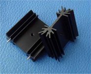
(Below) is what I've seen even on 20A industrial power supplies costing 1K$ or
more. These also are common on ebay/DIY modules.
If the builder was at the >20A or greater level , the external full bridge option
would be used.
OS
Attachments
I figured they wouldn't run very warm. My concern is that most likely the input end would be the bottom. Any heat disipation would be straight into the caps.
I figured they wouldn't run very warm. My concern is that most likely the input end would be the bottom. Any heat dissipation would be straight into the caps.
I'm doing the opposite , my rectifiers feed into the caps from the top and the outputs
to the amps come out the bottom.
BTW - those Kypton-C's are nice. - I will finally hear a true CFA. I see the reversed
LED pads. How did Y'all wrap your output coils ? I'm at the IPS/driver stage bench
test stage now ....
OS
I wrap around an Ultra Fine Point Sharpie marker. A 3/8" bolt would work.
That'll work. I got anal .... sharpie is .4" , bolt is .375" . 20-24 turns would be
1.4-1.6 uH , according to this - Coil Inductance Calculator - 66pacific.com .
Way long ago - I think this was my "badger" recommendation.

OS
Go bigger diameter and you can go less turns. 20 turns will be 1 1/4" long in 16awg wire. won't fit unless you stand it on end.
jwilhelm,
That just doesn't sound right to me. A change in diameter shouldn't change the inductance I don't think, isn't it strictly the number of turns that sets the inductance. Unless you are building inductors for high current and have saturation I don't think the diameter changes much of anything besides the dcr impedance if I am remembering correctly.
That just doesn't sound right to me. A change in diameter shouldn't change the inductance I don't think, isn't it strictly the number of turns that sets the inductance. Unless you are building inductors for high current and have saturation I don't think the diameter changes much of anything besides the dcr impedance if I am remembering correctly.
Go bigger diameter and you can go less turns. 20 turns will be 1 1/4" long in 16awg wire. won't fit unless you stand it on end.
OK , AA battery is .55" /@14mm .... so 15 turns = 25mm long = the same 1.6uH.
OS
I've tried it with a bunch of the on line calculators they say it does make a difference. The length of the coil works counterproductivly too. Longer physical length equals less inductance.
OK , AA battery is .55" /@14mm .... so 15 turns = 25mm long = the same 1.6uH.
OS
22 mm is pin centers. The real killer is when you finish one that looks perfect only to discover it's wound backwards for the board.

Nope , the diameter of the coil seems to be the big one. Increasing the dia. from
.55 to .7 increases 1.5 to 2.3uH.
Tried 5 single layer coil calcs ... 😕 They all use { L= (d^2 * n^2)/(18d+40l) }
.55 to .7 increases 1.5 to 2.3uH.
Tried 5 single layer coil calcs ... 😕 They all use { L= (d^2 * n^2)/(18d+40l) }
or some similar formula. D= diameter.
OS.
OS.
What ? 😕
OS
These boards are bidirectional. Valery's are in on the left, out on the right.
Some boards have staggered holes at each end. I have seen where guys swear that winding counter clockwise gives a different result that clockwise.
Some boards have staggered holes at each end. I have seen where guys swear that winding counter clockwise gives a different result that clockwise.
That's a bunch of whooey ... directional resistors , anyone ? 😀
The direction of the whole coil .. I'll believe. (Self's book)
The only references to winding "voodoo" were in those sites that had NO formulea
to back it up (subjective ??).
OS
Some boards have staggered holes at each end. I have seen where guys swear that winding counter clockwise gives a different result that clockwise.
Maybe that depends on which hemisphere you live in 😛. Gotta wind 'em CCW south of the equator...
Last edited:
LOL
There was a big argument about that in one of the threads I follow a while back. It was the usual suspects.
There was a big argument about that in one of the threads I follow a while back. It was the usual suspects.
- Home
- Amplifiers
- Solid State
- Slewmaster - CFA vs. VFA "Rumble"