Hi Nino,
I went through AK4118A datasheet and it specify TVDD minimum power supply of DVDD = 3.3V and typical 5V, maybe I'm reading it wrong, but of course even if, it doesn't saying anything about possible improvement 😉
Hi Munkyone,
fortunately TVDD pin has pretty good access so there is enough space to cut traces and make other connection if necessary...
I'm trying to make sense of all this... Some say that using 5V on TVDD can damage the receiver chip. Mine is already supplied with 3.3V Linear regulator, why are we talking about 5V now?
The spec sheet says clearly that AVDD typical is 3.3V and a max of 3.6V. DVDD should not exceed AVDD supply voltage so we assume 3.3V here and then TVDD min is DVDD voltage but max is 5V. What good will it do to drive it at 5V?
I'm all mixed up 😕
Thanks for any clarification
Do
Last edited:
Hello NinoSimona,AK4399 only accepts 24 and 32 bit I2s. 24 bit I2s works fine on my Arduino MCU atm.
Was the included MCU work in terms of switching the input or filter? I just finished my DAC today and powered on. Started playing right away. The thing I noticed was no change when I hit any buttons on the MCU / LCD board.
I would be happy to help on your Arduino journey.
Cheers!
Kumar
I'm trying to make sense of all this... Some say that using 5V on TVDD can damage the receiver chip. Mine is already supplied with 3.3V Linear regulator, why are we talking about 5V now?
The spec sheet says clearly that AVDD typical is 3.3V and a max of 3.6V. DVDD should not exceed AVDD supply voltage so we assume 3.3V here and then TVDD min is DVDD voltage but max is 5V. What good will it do to drive it at 5V?
I'm all mixed up 😕
Thanks for any clarification
Do
Pinnocchio, look at NinoSimona's post #761 on page 77. The smallest thumbnail shows that the max high level input voltage "VIH" is TVDD. So if VIH is 5V and TVDD is only at 3.3V then VIH is above max. The datasheet doesn't say what are the consequences.
Just a question: the regulator we take 5V current (green wire in Terranigma pic) from in your mod is LOD5 in DAC's schematics? Or what else?
Luca72C: either as shown in post #776 or #779, same source just different trace (right pin on LDO), I do not have 4113 schematics so can't confirm...
Last edited:
Nobody knows what LDO is it in DAC's schematics?
Is that the same 5V source that feeds XMOS board?
Is that the same 5V source that feeds XMOS board?
Last edited:
Hi Nino,
you are right, again 😉
Hi keres,
it looks like it's needed...
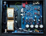
Hi Monkyone
look at this picture, you can see TVDD pin marked, also traces, no need to cut any traces just take the first coil off and you can solder new wire in from your 5V supply, not sure if TVDD needs any additional filtering cap
Kukynas. Thanks again. I think I will try it without a filter cap first.
Munkyone: I would suggest to add 47uf cap as mentioned in schematic just in case 😉
Luca72c: it looks like...
Luca72c: it looks like...
Munkyone: I would suggest to add 47uf cap as mentioned in schematic just in case 😉
Luca72c: it looks like...
Thanks Kukynas. The mod is on hold now... due to a momentary lapse of concentration while taking preliminary measurements, I shorted pins 3&4 of the LT1963 reg, with the meter probe. It now outputs 11.73v!! So now I need to determine if I will need a new AK4118 as well as a new reg 😱 More DIY fun and games 🙂
Munkyone: jeees, feel sorry for you 🙁 , btw. what's your digital transformer supply? did you follow suggestion from Weiliang to use 9V? make sure that first LT1085 from left side (close to LM7805 reg) is also measured as it is direct supply for LT1963A
Last edited:
Munkyone: jeees, feel sorry for you 🙁 , btw. what's your digital transformer supply? did you follow suggestion from Weiliang to use 9V? make sure that first LT1085 from left side (close to LM7805 reg) is also measured as it is direct supply for LT1963A
These things happen. Thankfully very rarely 🙂
I am using a 2x9v r-core. Thanks for the info. I will measure the 1085 also. I knew the reg was dead when I heard the transformer buzz.
Last edited:
Hi Kumar,Hello NinoSimona,
Was the included MCU work in terms of switching the input or filter? I just finished my DAC today and powered on. Started playing right away. The thing I noticed was no change when I hit any buttons on the MCU / LCD board.
I would be happy to help on your Arduino journey.
Cheers!
Kumar
At first I decided to build my own MCU, because I'm going to use an old digital tuner enclosure for my DAC; I'm using its LED display and other indicator LEDS. Also I didn't like the original LCD display.
At the moment I'm programming the Arduino to serve as replacement of the original controller. I'm going to add volume control to the DAC. The controller uses the original LCD display and the 3 switches. If I succeed and it all works fine, the program can serve as starting point for further functions (e.g. remote control, volume control with rotary encoder, I2s input, external muting relay).
My controller isn't a drop in replacement, there are adjustments needed to the hardware as well.
There must be a wrong connection if your buttons do nothing. You must be able to change source and filter with the original MCU.
Regards
Nino
Last edited:
Hi Kumar,
At first I decided to build my own MCU, because I'm going to use an old digital tuner enclosure for my DAC; I'm using its LED display and other indicator LEDS. Also I didn't like the original LCD display.
At the moment I'm programming the Arduino to serve as replacement of the original controller. I'm going to add volume control to the DAC. The controller uses the original LCD display and the 3 switches. If I succeed and it all works fine, the program can serve as starting point for further functions (e.g. remote control, volume control with rotary encoder, I2s input, external muting relay).
My controller isn't a drop in replacement, there are adjustments needed to the hardware as well.
There must be a wrong connection if your buttons do nothing. You must be able to change source and filter with the original MCU.
Regards
Nino
Hi Nino,
Thanks for your reply. I will check the connections on the LCD board. Can you please post a picture of your component side of the LCD / Controller board? I have some components missing in the kit and would like to compare it against yours since you got them assembled.
Regards,
Kumar
Look in kukynas' gallery.. Can you please post a picture of your component side of the LCD / Controller board? ..
These things happen. Thankfully very rarely 🙂
I am using a 2x9v r-core. Thanks for the info. I will measure the 1085 also. I knew the reg was dead when I heard the transformer buzz.
Kukynas: I think the 1086 reg is ok. In-situ it measures approx. 2.05v at pin 2 (Vout) and 6.02v at pin3 (Vin). All three 1086 measure same. Reasonable chance the 4118 is fried, so will source another anyway.
Vin must be around 11Volt for 9V AC transformer. Vout must be 5V. I think you must check your meter... or else you fried the transformer?
Munkyone: that's weird, these are LT1085 +5V regulators as mentioned by Nino so either something's wrong with you meter or you fried more things at the same time
Munkyone: that's weird, these are LT1085 +5V regulators as mentioned by Nino so either something's wrong with you meter or you fried more things at the same time
NinoSimona: Kukynas: Thanks, my mistake! I just checked the meter, which is ok. I checked the transformer; ok at 10.2v on both secondaries. I must have used the wrong ground ref when measuring the 1086s. Where would you recommend?
- Status
- Not open for further replies.
- Home
- Source & Line
- Digital Line Level
- ebay:Weiliang Dual X2 AK4399 DAC with LCD