Hi,
I got a huge problem with my integrated amp made by MAS.
As soon I'm starting to move stepped attenuator I can hear horrible cracking noise. Before I had normal alps pot I had same problem.
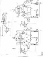
Please take a look a the diagram and advise me what resistance I should use for volume and balance control, as values are not indicated in the diagram.
Regards,
Mike P
I got a huge problem with my integrated amp made by MAS.
As soon I'm starting to move stepped attenuator I can hear horrible cracking noise. Before I had normal alps pot I had same problem.
Please take a look a the diagram and advise me what resistance I should use for volume and balance control, as values are not indicated in the diagram.
Regards,
Mike P
Attachments
Is this problem the same with inputs disconnected? Is the input signal still audible otherwise?
This is a DC coupled (no isolating capacitors) input so any DC anomaly or disturbance at the source or in the wiring becomes a part of the input signal. Perhaps this is the source of the the crackling noise or if mistakes have been made in replacing the pot, there may be damage to the amplifier and exposed like that, it's very easy to do damage unawares.
If you fitted the stepped attenuator, it must surely have been selected to match the pot it replaced and pots of all brands have marked values, so this is not difficult.
if attenuator is having same or lesser resistance as pot originally used , also made with make-before-brake switches , there can't be a problem
Hi,
Thanks for replay and ideas.
When I got this Amplifier it came with volume and balance control swapped from resistors ladder, to normal pots (poor quality ones).
At the beggining I replaced those pots to resistors ladder (same value as pots), but it didn't rule out noise during changing volume.
Please have a look on that diagram I added; balance pot is in the feedback loop, rather than in series with pot.
Pot for volume control was 10k and ones for balnce-50k.
Balance was working very poorly; I assume that the value might me incorrect or wrong type pot was used (log instead linear or vice wersa).
I tried to get rid of balance pot, using 2x25k resistors, but it didn't resolve problem with craking noise.
I'd rather stick with the oryginal desing since MAS normally knows what they're doing.
Will it help if I make some PCB photos?
can you measure if there is a volt drop (Vdc) across the vol pot (against ground)?
how big is the offset voltage (Vdc) at the output of the amp (without speaker load)?
how big is the offset voltage (Vdc) at the output of the amp (without speaker load)?
The balance controls in the feedback loop are also at DC if there is any DC offset at the output, meaning they will interact if there is a problem at the input with DC signal, as well as if there is a problem in the amplifier.......balance pot is in the feedback loop, rather than in series with pot....
Have you removed the input leads yet to check the effect?
Do you have a digital voltmeter to measure anything?
Can you link the schematic or increase the size of the image as it requires magnification. (too blurred to read though, even on a 24" screen).
Please reply or say whether you understand the questions or not.
Last edited:
It appears that the problem may be caused by DC flowing through the volume control.To overcome this a 100 k ohm resistor should be connected to ground from the Q1 and Q3 bases ( the same for Q2,Q4) and a ,say, 10 microfarad film capacitor fitted between the wiper of the vol. pot. and the junction of R13/C1 (also R16/C2).The value that you choose for the vol. control is not critical, if all of the associated sources are of a low impedance.A value of 10 K ohm is normally o.k..What is needed,is a control that gives a broad transistion from silence to loud and this is usually via a log. scale.
Thank you for your effort to help me with this hiccup. Ian, I do understand your suggestions. I will try check all ideas tonight and share findings. Thanks again,
MikeP
MikeP
Hello,
After a break I can go back to my amp 😉
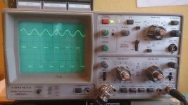
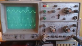
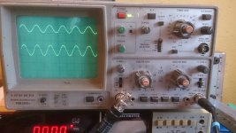
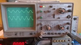
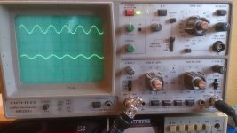
Please have a look on pics I added. This is showing an imput signal (on the top) and output signal (at the bottom). During whole test the input singnal values are constant; they are 1V and 1kHz.
"step 0" showing, when volume ctrl ladder is max on the left
"step 1" to "step 22" showing following steps on volume contol, hovever the output setting has changed on "step 6"; 5V/DIV., "step 9"; 10V/DIV., "step 12" to "step 22"; 20V/DIV.
Please note, that since step 13 the output signal hasn't changed its size, but sinewave top got more flat with every step, until step 22, where it looks more like square than sine. Is this correct?
I checked the DC on speaker terminals and value range between 4mV (can be meter error) to 75mV as I changed volume up. I also noticed, that during switching between steps, the bar on my mulitmeter, (showing DC in real-time measurements) grows rapidly (for less than second) and drop. this is happening on every step, and is bigger as the resistance of the volume ctrl goes down.
After a break I can go back to my amp 😉
Please have a look on pics I added. This is showing an imput signal (on the top) and output signal (at the bottom). During whole test the input singnal values are constant; they are 1V and 1kHz.
"step 0" showing, when volume ctrl ladder is max on the left
"step 1" to "step 22" showing following steps on volume contol, hovever the output setting has changed on "step 6"; 5V/DIV., "step 9"; 10V/DIV., "step 12" to "step 22"; 20V/DIV.
Please note, that since step 13 the output signal hasn't changed its size, but sinewave top got more flat with every step, until step 22, where it looks more like square than sine. Is this correct?
I checked the DC on speaker terminals and value range between 4mV (can be meter error) to 75mV as I changed volume up. I also noticed, that during switching between steps, the bar on my mulitmeter, (showing DC in real-time measurements) grows rapidly (for less than second) and drop. this is happening on every step, and is bigger as the resistance of the volume ctrl goes down.
Attachments

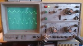
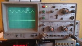
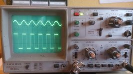
All that is being shown on the CRO screen is clipping overload.To determine the clipping point and sensitivity of the amplifier with say, a resistive load of 8 ohm;set the attenuator for maximum gain and adjust the level of your input signal from zero to a level where clipping just occurs.Something may be concluded after this particular revision,but I am not sure what you are trying to achieve.
- Status
- Not open for further replies.
- Home
- Amplifiers
- Solid State
- Metaxas Ikarus; problem with volume control