MOSFETs have a smoother characteristic than BJT. The big snag with MOSFETs is that you can't buy any two (same or complementary) which have the same characteristics, whereas (to a first approximation) all BJT are exactly the same.
Yes, I just look at one issue at a time.
I am going to change the subject a little: Is there any consensus which is better in sound quality between MOSFET and BJT followers OPS?
I understand MOSFET has a much bigger variation, but the good thing is they are kind of self thermal compensate as the one that conduct more gets hotter which then decreases the turn on voltage to lower the current itself. BJT goes the opposite way as it conduct more as temp goes up and can get into thermal run away.
I am planning to build one tube and one SS. I am still deciding between BJT or MOSFET. If I go MOSFET, I will buy double the amount of transistor and hand test to pick the matching transistors. I think all I have to do is build a test jig that run the transistor at say 1A and measure the Vgs.
After scanning through a 2 inch pile of output tube datasheets, these were the only ones that gave a gm graph (last graph page):
http://tubedata.milbert.com/sheets/135/6/6HB6.pdf
http://tubedata.milbert.com/sheets/123/1/10JA5.pdf
http://tubedata.milbert.com/sheets/123/6/6LU8.pdf
You can sum two of the gm curves (one reversed, and positioned by bias V) to get gm "wingspread" diagrams like Self or Cordell have in their books for BJTs and MosFets. Obviously only class A comes close to constant gm for minimal distortion.
But compare a typical Tube gm curve versus the BJT and MosFet gm curves in Self's book (6th ed. page 502). Only the tube has a smooth transition to zero gm at low current. So sharp kinks in the crossover region are avoided for class AB with tubes. So these are easier to iron out with some N. FDBK.
Thanks so much of your time. So far, sounds like Tube does have advantage over SS in a lot of area. With mu-follower or Beta follower, you can get very low distortion from a triode gain stage.After scanning through a 2 inch pile of output tube datasheets, these were the only ones that gave a gm graph (last graph page):
http://tubedata.milbert.com/sheets/135/6/6HB6.pdf
http://tubedata.milbert.com/sheets/123/1/10JA5.pdf
http://tubedata.milbert.com/sheets/123/6/6LU8.pdf
You can sum two of the gm curves (one reversed, and positioned by bias V) to get gm "wingspread" diagrams like Self or Cordell have in their books for BJTs and MosFets. Obviously only class A comes close to constant gm for minimal distortion.
But compare a typical Tube gm curve versus the BJT and MosFet gm curves in Self's book (6th ed. page 502). Only the tube has a smooth transition to zero gm at low current. So sharp kinks in the crossover region are avoided for class AB with tubes. So these are easier to iron out with some N. FDBK.
Usually tube power amp consist of 1st gain stage, PI stage and OPS stage. It seems to me if I use Beta follower as first stage ( using MOSFET as the top tube), regular long tail pair with BJT CCS tail as PI. Then use UL output stage. I should get superior low distortion compare to SS power amp. Is that the case?
Thanks
A tube output stage will always have more distortion than a SS one, because of the output transformer.
Going OTL doesn't fix this, you just run up against the problem that the output stage can't be symmetrical, because there are no P-channel tubes.
Going OTL doesn't fix this, you just run up against the problem that the output stage can't be symmetrical, because there are no P-channel tubes.
A tube output stage will always have more distortion than a SS one, because of the output transformer.
Going OTL doesn't fix this, you just run up against the problem that the output stage can't be symmetrical, because there are no P-channel tubes.
Scopeboy
For OTL SEPP ( Single Ended Push Pull ) OPS that can be the truth since P-channel tube not exist , but check for Circlotron PP OPS , it is fully symmetrical and balanced OPS .
But going OTL also includes another sets of problems and solutions regardless to chosen tube OPS configuration .
There is a way to make a totem pole tube output stage act in a balanced way too (besides Circlotron). A pentode LTP driver stage drives the grids of both stacked output tubes. But, the LTP load resistor for the top tube grid drive gets bootstrapped up top by the actual output. Then everything sees equivalent gains.
--------------------------------------------------------------------------
For OTL there are some "intelligent OTL" options to fix the current drive issue. Essentially a SS amp, with complementary Collector or Drain outputs, drives the speaker output in current drive mode. Ie, high impedance output. The tube amp then drives the same output point in voltage mode. The SS current drive gains get adjusted to minimize the current drawn from the tube amp. So the tube amp only sees residual current loading, hence high Z. (so you can make an "OTL" amp with two modest tubes!) This can still be a high damping factor setup, even with a smallish tube V amp, if the current control sensing for the SS I amp comes from the tube amp speaker return ground. (the SS feedback tries to zero the current there)
The other approach is to use a conventional SS voltage amp and connect the tube V amp in series using a very low output secondary Z OT. (not strictly OTL obviously, but the damping factor will still be high here) The Tube voltage amp takes its Neg. feedback control from the output sum point going to the speaker, so it makes sure the final output conforms to ITs wishes. The tube amp sees very little loading due to the very low secondary Z winding reflecting high Z at the primary. (ie, very large current ratio from large turns ratio) This approach also allows one to use a smallish/moderate tube output stage. (depends on the OT secondary Z as to how much power is contributed by the tube amp.)
These approaches were suggested over ten years ago, but I don't think anyone has built one.
Last edited:
Member
Joined 2009
Paid Member
I believe - am pretty sure - that you can build a superb sounding amplifier with either tubes, BJTs or MOSFETs and trying to choose between them which approach is best, based on opinions and the odd bit of science is not the best way. In my opinion, a better approach is to pick a technology that you are confident with, that you can design with to the best of your abilities. If that is MOSFETs then you'll get the best results with MOSFETs. If your forte is BJTs then you'll get the best results with BJTs. All these approaches have been proven to sound very good to enough people to convince me that they are all equally valid approaches.
Last edited:
I guess,
the diode options don't apply..😀
There is:
the rh zener, the electron stream diode triode and U/L.
The true triode..etc. ccs cathode and more..
Regards
M. Gregg
the diode options don't apply..😀
There is:
the rh zener, the electron stream diode triode and U/L.
The true triode..etc. ccs cathode and more..
Regards
M. Gregg
Last edited:
"I believe - am pretty sure - that you can build a superb sounding amplifier with either tubes, BJTs or MOSFETs......."
Definitely. One should have a good understanding of how each type works. Then one can comfortably apply the best solutions to any type circuit.
The tube amp genre is interesting because it uses parts that are big enough to see, looks nice, can be hand wired, sounds nice and will keep you warm on a cold Winters' night. You can build workable good sounding designs that don't require all the feedback stability analysis of high gain SS designs. And there is still some room for experimenting, innovations with a little SS added in, and just fun mods. Generally easier to get a good working amp too, and tolerant of many mistakes. Just don't get electrocuted!!
--------------------------------------------------------------
diode options?
I'm guessing this has something to do with UL?
There is a diode trick one can play with BJT outputs. Put an old TV damper diode in series with the base terminal and get tube like gm curves.
Last edited:
Well guys, I started a thread in the SS part of the forum and ask the SS people why they consider SS wipe the floor with tubes. Please join in.
http://www.diyaudio.com/forums/solid-state/265720-ss-vs-tube-power-amp.html
I am actually a lot more familiar with SS than tubes. I read the book by Cordell in detail analyzing of distortion in SS amp. I am reading Morgan Jones and read about using mu and beta follower to make horizontal load line for triode. I don't see SS wipe the floor with tubes. Together with the superior performance of tubes in crossover department. I question the truth about "SS wipe the floor with tubes". So I hope the people in SS can give me more insight to convince me SS is better.
I don't have preference between SS and tubes, and in all likelihood, I am going to build one of each.
These types of "which is better" discussions have gone on many times before and usually degenerate into subtle "un-measurable" effects versus X number of 0's in the distortion spec. You really have to build a tube amp to begin to appreciate the experience and fun. Much like driving an old fancy Bugatti versus a modern Tesla. Having worked with tube and SS I don't try to compare which is better, they are simply different experiences.
These types of "which is better" discussions have gone on many times before and usually degenerate into subtle "un-measurable" effects versus X number of 0's in the distortion spec. You really have to build a tube amp to begin to appreciate the experience and fun. Much like driving an old fancy Bugatti versus a modern Tesla. Having worked with tube and SS I don't try to compare which is better, they are different experiences.
I don't disagree, I just want to hear from the SS people analytically why "SS wipes the floor with tubes".
It is easier to build a tube amp. I can just do point to point wiring. I build tube guitar amps like that. But I need to do pcb with SS power amp. Tube amp is much more expensive compare with SS.
Well, there is no doubt that SS can do PPM distortion specs and tube amps generally not. It is more of a trade off of starting with something quite linear (tube) and not having to go to extremes (high loop gain NFBK) or complexity to get "good" sound with tube amps.
Then there are endless arguments about "subtle" effects from extreme NFBK and trying to fix defects, which I only partially buy into. One could try to build a tube amp with extreme local NFBK and modest global NFBK, but what is the point? It will just sound like a Wal-Mart SS amp then.
On the cost issue, sure, you can spend a bundle on a tube amp easily. There is a sub-group here (myself included) who like to use cheap TV Horizontal output tubes ($1 sometimes) and often unconventional amp designs (typically local FDBKs) to get around cheap OT deficiencies. One can definitely make a good tube amp with cheap parts if one is smart about it. Part of the fun and challenge. But 1st you need to learn the issues and fixes available to get away with this "Pirate" behavior. George (Tubelab) is one of the well known hot-rodders, many others here too.
The chassis can be an expensive component for both SS or tube, but can be cut back to a cake tin or surplus unit. The power supply is another expensive area for tube, but could be done using a SS switcher if well filtered. I have gotten some remarkable SS HV switchers off Epay, made for NASA solar panel testing by Xantrex. Many other low cost options like industrial xfmrs. The OT is the primary focus for tube performance/price. Local feedback and attention to distributed capacitance and primary and leakage reactances of unconventional OTs can keep price in reason. Then, for the really SS talented, there are some switching OT designs that use ferrite and Mosfets. Even a capacitance V multiplier circuit can be used as an OT.
Last edited:
There is a way to make a totem pole tube output stage act in a balanced way too (besides Circlotron). A pentode LTP driver stage drives the grids of both stacked output tubes. But, the LTP load resistor for the top tube grid drive gets bootstrapped up top by the actual output. Then everything sees equivalent gains.
--------------------------------------------------------------------------
Smoking - Amp
What do you think about this ? :
It is the upper output power tube in that `balanced` AB class SEPP power bridge always just one modulated power CCS for lower output power tube , which ( ideally )contribute 50% distributing power into the load(speaker), but in the same time lower output power tube is just one power SE(T) OTL stage with active modulated tube based power CCS in his anode circuit ? ,
Where output dynamic THD spectrum and overall OTL amp sound is expected to be more as from some SE(T) amp type than from some pure PP amp ?
I don't disagree, I just want to hear from the SS people analytically why "SS wipes the floor with tubes".
Another waste of time...whats the point?
you are back to sound quality Vs measurments..another waste of time because the system is a unit and the individual parts can interact differently..you don't take account of the total system part of which is you!
Its like asking someone to pick a HIFI for you..you might think its great until you hear someone else's..
What about saying that a band sounds better on your hifi than live on stage..a live recording is not as good as a studio recording..or the system is lacking in some respect...
The only thing that matters is do you like what you hear!
For me if it doesn't move me emotionally then I'm not interested..the same would be true of a live performance..if it doesn't move me whats the point in being there?
The question is this..are you listening to the music or the equipment?
Regards
M. Gregg
Last edited:
"What do you think about this ? :"
The bootstrapped LTP driver scheme mentioned above removes the output voltage effectively from the upper totem pole circuit. So it ends up like two conventional grounded cathode stages. (Broskie has an article on this somewhere, along with his famous move the ground around technique to explain it all)
But sure, one could make a V stage and controlled I stage combo too. Wavebourn has been an advocate of this approach. Just a CCS would be inefficient. But a controlled current source combined with a controlled voltage source can be efficient and give SE like effects, since the V stage alone sets the output V. Nelson Pass has some all SS versions of this setup.
If you did use the bootstrapped LTP driver scheme with a pentode and triode outputs, you would effectively get controlled V and I sources. A big improvement over parafeed inductors or inefficient CCS or R pullups for SE stages, since a conventional OT could be used, and twice the power out of just the SE stage alone. The controlled current source side needs to be fairly linear in order not to alter the SE sound from the SE triode stage.
You could just put a triode on one side of a normal P-P OT, and a controlled pentode on the other side to get the same effect.
Last edited:
"What do you think about this ? :"
The bootstrapped LTP driver scheme mentioned above removes the output voltage effectively from the upper totem pole circuit. So it ends up like two conventional grounded cathode stages. (Broskie has an article on this somewhere, along with his famous move the ground around technique to explain it all)
But sure, one could make a V stage and controlled I stage combo too. Wavebourn has been an advocate of this approach. Just a CCS would be inefficient. But a controlled current source combined with a controlled voltage source can be efficient and give SE like effects, since the V stage alone sets the output V. Nelson Pass has some all SS versions of this setup.
If you did use the bootstrapped LTP driver scheme with a pentode and triode outputs, you would effectively get controlled V and I sources. A big improvement over parafeed inductors or inefficient CCS or R pullups for SE stages, since a conventional OT could be used, and twice the power of just the SE stage alone.
Yes , that was exactly what I was thinking to .
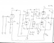
and here is my fast scratch simplified schematic , where basically Mullard 5-20 front end is adapted to drive SEPP OTL power bridge , and of course V1 can be some AF pentode same as for bootstrapped LTP phase inverter /driver stage .
Attachments
Last edited:
Yes, however using two triodes for outputs will act like a normal P-P stage with the even harmonics cancelling. You would need a pentode for one of the outputs to get something like a SE sound effect if that is what you want.
I think the Futterman or anti-Futterman OTL design is essentially what you have there. Details may be different for the front end.
I just looked up Futterman circuit and it used a bootstrapped Concertina PI. Actually bootstrapped on the bottom for the top output tube drive, so was increasing gain to match in that case. I guess the anti-Futterman puts the bootstrap to the top of the PI to reduce gain there to match.
Ahh, anti-Futterman is missing the crossed grid drives off the PI, so reduces gain for the bottom output tubes, then puts in another gain stage ahead of the PI to make up.
Last edited:
Yes, however using two triodes for outputs will act like a normal P-P stage with the even harmonics cancelling. You would need a pentode for one of the outputs to get something like a SE sound effect if that is what you want.
I think the Futterman or anti-Futterman OTL design is essentially what you have there. Details may be different for the front end.
I just looked up Futterman circuit and it used a bootstrapped Concertina PI. Actually bootstrapped on the bottom for the top output tube drive, so was increasing gain to match in that case. I guess the anti-Futterman puts the bootstrap to the top of the PI to reduce gain there to match.
Pentode for upper modulated power CCS will be good match in this configuration , except that pentode will need extra G2 PSU referenced to her cathode for full effective operation , which can even more to complicate overall design , but some power N type- LatFet with his pentode transfer characteristic can be used there instead of tube successfully.
And yes you are correct, anti-Futterman ( but not Technics variation) use bootstrap for upper part of Concertina PI .
Last edited:
Again, a few marginal notes;
1. The (mostly) maligned OPT:
I cannot agree about this component's MAJOR contribution to distortion. Not overly expensive OPTs have distortion at full output of <1% - often lower than the contribution of the power tubes. While probably the most expensive component in tube amplifiers, it has an unjustified reputation as the chief crook in the tale. (We seem to have temporarily gone off the thread topic ...)
2. SS vs tubes:
This is a largely 'apples vs oranges' affair. The two topologies are different, and both can easily be designed to give inaudible distortion. (It is still about audio - isn't it?) In that perspective the achievement of 0,umpteen zeros% distortion is academic; perhaps for instrumentation amplifiers and promotional rhetoric.
Many notions regarding this comparison relies on existing commercial amplifiers. Tube amplifiers are often preferred because of a 'musical' or 'warm' sound, i.e. taste (such experiences often result from enough 2nd harmonic and some 3rd harmonic distortion to give a 'nice' sound). No objection against taste, only let us call it what it is. It seems to have become the norm to accept tube amplifiers quoting some ½% - several % distortion. Where are the days when 0,1% was accepted to be a standard; 0,3% already detectable?
3. Regarding the cross-over region:
Again I must be missing something about its present-day threat. All previous arguments accepted, but it is utterly possible to design a class AB SS amplifier with negligible cross-over distortion (and what there is, as in 0,005% at around 1W output, devoid of high-order products). Been there done that, and I certainly do not expect to be considered for a Nobel Prize.
Yes, easier with tubes because of the more gradual gm decline; still as above. Not to sound arrogant, but why is this still considered a serious problem? (Constant gm is another matter, but that is not nearly a requirement. One gets by perfectly with an often 60% variation in gm over the operating region of many voltage amplifier driver tubes - just look at graphs of gm-, rp- and µ-spread for many triodes.)
To me: It is obviously more economical to design a blameless SS amplifer than a tube one. Yet I have done both, at least to the satisfaction of customers ....
- Status
- Not open for further replies.
- Home
- Amplifiers
- Tubes / Valves
- Comparing OPS.