tested it with 100k and 10k resistor with caps. seem to sound better but still abit distorted.
does need to have the cap tho if not the voltage goes back up.
does need to have the cap tho if not the voltage goes back up.
haha ok nevermind it does work. just sound crap on the cheap test head phones i was using. too low resistance head phone. didnt want to plug better one in with out it breaking haha
well cant say its the best sounding thing but at least it works
Thanks alot guy especially Mooly for the help an advice.
Ill probably try swapping out the OP sometime in the future but till then ill keep fiddling around with different resistors and cap as what u guys have suggested and see what happens.
Thanks guys
That's good to hear its working of a sort. Best advice for this amp is to run it on a higher supply voltage (make sure caps and the rail splitter IC are suitably rated) and also add some low value series resistors to each phone output, say 47 to 100 ohm. That will ease the loading on the opamp and the higher supply means it can deliver greater voltage swing into the now higher impedance load. Its a win win situation and it would sound much better.
I did some tests on how much voltage was needed for my quite efficient Sony MDRV-7 headphones and found it to be around 0.8 volts peak to peak.
That's not much, but again lets put some numbers in. 0.8 volts pk/pk is 0.4 volts pk. 0.4 volts across say 30 ohms is a current of 12.5ma. That is getting to about as a much as typical opamp can deliver current wise. Inefficient phones need more voltage... and so the current increases too and with an opamp limits out (which is distortion of course). Running an opamp on just 9 volts (on a good day when the battery is new) is worsening the situation as a well.
If you want a good headphone amp then the 02 (there is a big thread on this amp) is pretty decent and would make a nice project as boards are available.
Just noticed what forum this was in 🙂 Moved to Headphone forum and here is the link to the O2.
http://www.diyaudio.com/forums/headphone-systems/193977-objective2-o2-headphone-amp-diy-project.html
http://www.diyaudio.com/forums/headphone-systems/193977-objective2-o2-headphone-amp-diy-project.html
O kool, ill take a look into the O2 but its gonna be a long read. over 400 pages 0_o
could be my next project haha. lots to read and learn
yeah alot of site say that op should run on 18v so yeah i might try adding an other 9v later in series and see how thats goes
could be my next project haha. lots to read and learn
yeah alot of site say that op should run on 18v so yeah i might try adding an other 9v later in series and see how thats goes
18 volts supply and the added series resistors would make a world of difference.
The 02's a pretty good design and would make an ideal project built on the official boards.
The 02's a pretty good design and would make an ideal project built on the official boards.
Yes, doing that will reduce (but not totally eliminate) the offset. The cap maintains the AC gain but reduces the DC gain to unity (a gain of 1).
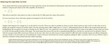
To fully minimise the offset you would have to make the 20k's into 100k (to equalise the input currents) and make the 2k's into say 10k to maintain the gain. Its the ratio of those two that sets the gain. Another very workable solution would be just to replace R2 (100k's) with 20k's. The only real downside is that doing that would change the "law" of the volume control but that only means it feels a little different with rotation angle vs loudness. That could be an ideal solution actually, just replace those resistors with something close to 20k (18 or 22k are common values). And keep the AC coupled feedback.
So to minimize the offset with bipolar-input op-amps, R2 and R4 should be the same value, right?
If so, that's seems like a MUCH easier way of determining the values of 2 out of the 3 resistors, rather than trying to understand all the formulas in the image below.
Thanks...
Attachments
So to minimize the offset with bipolar-input op-amps, R2 and R4 should be the same value, right?
Right 🙂 well actually no 😛 That only works if the feedback return is AC coupled (cap in series with R3)
If you want it all DC coupled then you have to use those formulas which aren't that scary. Its just the parallel resistor formula, "product over sum" is the quick way to remember it.
If we kept the 2k DC coupled then R2 would need to be 1818 ohms for minimum offset. That's because the opamp output is at 0 volts and so is ground of course. So the - input sees those two resistors as being in parallel as far as bias current is concerned. The problem now is that becomes the input impedance of the circuit... which is to low for audio.
The only real downside is that doing that would change the "law" of the volume control but that only means it feels a little different with rotation angle vs loudness
Mooly, what do you mean by this? Will the volume get louder with less rotation of the pot, or what?
Also, will a 100uF cap in the feedback loop affect the sound like a coupling cap in series with the noninverting input?
Thanks...
If the volume is already a log type, then adding a resistor from the wiper to ground and whose value is relatively low in value (compared to the pot) will change the logarithmic law somewhat. All that means is that the wiper voltage vs rotation follows a slightly different curve.
If the pot is linear then the resistor (if you get the value right) can give a really good approximation of a log pot and is a preferred solution really because log pots can often have poor tracking between the two gangs of a stereo pot.
The cap in the feedback return causes the response of the amp to fall away at low frequency, similar to having a cap in the input feed. The big difference between the two is that the feedback cap reduces the opamp gain to unity at DC. The input cap doesn't, the basic circuit has the full gain at DC, hence the offset problem. With correct choice of values there should be no problem with sound quality.
found a really good read here too
NwAvGuy: Cmoy With Gain
You will find a lot of information in this read. Well worth the learning experience for a newbie.
To make a long story short, NwAvGuy recommends that you use the JRC4556A chip. He uses it in the O2 headphone ampllifier, which is not that different from the cMoy.
The main reason for this choice is that its output impedance and far lower than any other IC's normally mentioned, and will match virtually any headphone. He backs this up with measurements. The choice is simple. This is the only low priced IC that provides sufficient current for almost any headphone. Use it.
I have used this chip as a buffer so that the gain is 1. Even that is too much for my headphones.
To make a long story short, NwAvGuy recommends that you use the JRC4556A chip. He uses it in the O2 headphone ampllifier, which is not that different from the cMoy.
The choice is simple. This is the only low priced IC that provides sufficient current for almost any headphone. Use it.
The NJM4556A may provide fairly high current output(70mA), but it's priced cheap for a reason...it sounds like crap.
The NJM4556A may provide fairly high current output(70mA), but it's priced cheap for a reason...it sounds like crap.
I'm sure you have arrived at this conclusion after doing thorough and honest "double blind" testing backed by objective measurements or maybe you have seen 0.5$/pc😱 price tag for NJM4556A. Thank goodness, I feel so blessed that I have "tin ears" to enjoy simple(read cheap) things like O2 or a CMOY instead of M3 or some esoteric / hybrid tube based amps or even something like http://www.gradolabs.com/headphones/headphone-amps RA1 Amplifier-List Price: $425 another NJM4556A based glorified CMOY.
Last edited:
The NJM4556A may provide fairly high current output(70mA), but it's priced cheap for a reason...it sounds like crap.
The 4556 can be configured for unity gain and nested with op amp of your choice for input. This is far superior to using the 4556 alone in a cmoy type headphone amp; the input device is doing the feedback error correction. You will probably have to Miller the input stage out around 250kHz or so in a nested configuration.
I read some old marketing literature claiming that the 4556 was an upgrade for a typical tone control circuit of the era (1990 or so). In fact in some circuits it might have been an upgrade; some tone control designs require the op amp to drive low impedance, highly reactive loads when the control is turned up. If you look at some circuits, the feedback impedance consists of a 1K resistor in series with a capacitor when the control is turned all the way up. Some older generation op amps had pretty low output current capacities, sometimes as low as 15 mA; so you would be running the output stage closer to maximum spec (and well into class B operation) which would certainly increase distortion.
I'm sure you have arrived at this conclusion after doing thorough and honest "double blind" testing backed by objective measurements or maybe you have seen 0.5$/pc😱 price tag for NJM4556
Price doesn't mean anything to me. If they were to cost $10 each, I would say the same thing about them.
I have tried it both as a noninverting gain stage and also as a buffer with other op-amps in front of it.
With that being said, I actually do like a couple of JRC's inexpensive op-amps, just not the 4556.
Also, I personally wouldn't pay anywhere near that price for that "Grado Labs" amplifier.
I'll leave them for the folks that have far more money than sense.🙂
It would help us if you gave an explanation of what op-amp sounded better in direct comparison with the 4556, and how you think it sounded better.
I have tried it both as a noninverting gain stage and also as a buffer with other op-amps in front of it.
When you used it as a buffer, did you nest it into the global feedback loop? It makes a big difference. I already pointed out the advantages.
But no matter what op amps you use, you're asking them to operate way outside of their operating parameters. Putting a low impedance load on the output stage of any op amp will increase nonlinearity, and reduce current gain. The only way around it is to use a proper output buffer- whether discrete or a device like the BUF634 or 49960. The 49960 is well worth the expense, because it is actually engineered to drive low impedance headphones. Also it is extremely fast so it you won't have to worry about Miller compensation of the input stage unless you choose an extremely fast op amp. For all the trouble it is to design and build something really good, it's a no brainer to me. 😉
- Status
- Not open for further replies.
- Home
- Amplifiers
- Headphone Systems
- First time building CMOY - Need some help