Hi guys,
I been lurking around for sometime looking for something to build and i saw alot of people recommending for first time builder to build a CMOY.
So i went and brought this cmoy kit off ebay to build.
DIY Classic Cmoy HI FI Stereo Headphone Amplifier TI OP LM833 Dual Audio AMP | eBay
The problem i am having is that it is giving off some terrible distortion when ever i try to play anything thru it and i have no idea why.
Ive checked all my soldering and they all look fine.
I have read many posts and the official cmoy page and started troubleshooting.
cmoy says the output should be no higher than 20mv between it and the ground, but for some reason i get 0.3v.
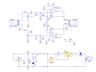
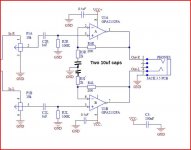
The diagram below was taken from another project but i have edited it with what is on the board and what i can see.
any help on this would be appreciated thank you
EDIT
btw this is using the LM833 chip and not the OPA2132 chip as shown in the diagram
I been lurking around for sometime looking for something to build and i saw alot of people recommending for first time builder to build a CMOY.
So i went and brought this cmoy kit off ebay to build.
DIY Classic Cmoy HI FI Stereo Headphone Amplifier TI OP LM833 Dual Audio AMP | eBay
The problem i am having is that it is giving off some terrible distortion when ever i try to play anything thru it and i have no idea why.
Ive checked all my soldering and they all look fine.
I have read many posts and the official cmoy page and started troubleshooting.
cmoy says the output should be no higher than 20mv between it and the ground, but for some reason i get 0.3v.
The diagram below was taken from another project but i have edited it with what is on the board and what i can see.
any help on this would be appreciated thank you
EDIT
btw this is using the LM833 chip and not the OPA2132 chip as shown in the diagram
Attachments
Last edited:
Hi guys,
I been lurking around for sometime looking for something to build and i saw alot of people recommending for first time builder to build a CMOY.
So i went and brought this cmoy kit off ebay to build.
DIY Classic Cmoy HI FI Stereo Headphone Amplifier TI OP LM833 Dual Audio AMP | eBay
The problem i am having is that it is giving off some terrible distortion when ever i try to play anything thru it and i have no idea why.
Ive checked all my soldering and they all look fine.
I have read many posts and the official cmoy page and started troubleshooting.
cmoy says the output should be no higher than 20mv between it and the ground, but for some reason i get 0.3v.
The diagram below was taken from another project but i have edited it with what is on the board and what i can see.
any help on this would be appreciated thank you
0,3V at output is to high for op-amp. May be some resistors is not connected / unsoldered. Please check all input inverting (2 and 6) and non inverting (3 and 5). It should be only several mV.
If you can made operating point right, than you can connect it to high impedance headphone (> 600 Ohm) to get reasonable distortion.
2 show 34mv. while 3 shows 28mv
3 show 33mv and 5 show 27mv
Ill take a another look at the solder and try reheating them to see if they sit better
So i have now resolder and checked all the points but still no luck. still getting the same voltage reading.
An externally hosted image should be here but it was not working when we last tested it.
The LM833 is a device with high (relatively speaking) DC input bias currents, typical of many "bjt" devices.
To minimise DC offset, the bias currents that flows out of the two input pins need to be identical, and that is achieved by making sure each sees the same DC "impedance". The 100k and 2k are hopelessly mismatched, and what is happening is that the opamp is amplifying its own offset error. The OPA opamps are FET devices and have no such issue.
(I wouldn't like to say at this stage whether you have other problems or not such as instability, but that circuit is not suitable for an LM833 as it stands)
Lets put some numbers in. DC gain of your circuit is (20000+2000)/2000 which is 11. The LM833 has a worst case bias current of 1000na (nano). So 1000na flowing through 100k develops 0.1 volt at the input. Amplify that by 11 and you get a DC offset (worst case) of 1.1 volts DC.
I'm afrayed you've been Ebayed.So i went and brought this cmoy kit off ebay to build.
DIY Classic Cmoy HI FI Stereo Headphone Amplifier TI OP LM833 Dual Audio AMP | eBay
btw this is using the LM833 chip and not the OPA2132 chip as shown in the diagram
 OPA2132 costs around $15US in small quantity and even OPA2134 is around $5US. LM833 or its cousin, NE5532, cost a mere $1 or so. Mooly has given you the technical reason and I'm sure you get the picture now, why cheap = bummer when it simply means skimping on specified quality parts. As the kit specifies LM833, you have no redress, unfortunately.
i kinda get what your saying but the whole impedance thing goes over my head sorry.
i was thinking of lowering the gain by swapping out the 20k resistor for a 10k so ill get a gain of 6.
hopefully that will help fix it if not would it be wise to change the chipset to an OPA2132 like what most people have?
i was thinking of lowering the gain by swapping out the 20k resistor for a 10k so ill get a gain of 6.
hopefully that will help fix it if not would it be wise to change the chipset to an OPA2132 like what most people have?
I'm afrayed you've been Ebayed.
haha yeah. well first time build these so its a learning curve.
so it would be better to get the OPA2134 to replace it then?
First thing... don't mess your board up... its far easier just to fit a FET device.
If you snip the 2k's and add a series 10 or 22uf cap to them then you AC couple the feed back and greatly improve the offset situation. If you do that then check the cap polarity by measuring the voltage across it even though its very small.
If you snip the 2k's and add a series 10 or 22uf cap to them then you AC couple the feed back and greatly improve the offset situation. If you do that then check the cap polarity by measuring the voltage across it even though its very small.
First thing... don't mess your board up... its far easier just to fit a FET device.
If you snip the 2k's and add a series 10 or 22uf cap to them then you AC couple the feed back and greatly improve the offset situation. If you do that then check the cap polarity by measuring the voltage across it even though its very small.
Ummm im a complete novice to this and kinda went over my head. im gonna have to google everything you just said 😕
ahhhh so just add two caps after the 2k resistor.
I got real lost when you started talking about AC couple feedback something....
Ill give that a go later tomorrow and will let you know how it goes.
Thank for the help
I got real lost when you started talking about AC couple feedback something....
Ill give that a go later tomorrow and will let you know how it goes.
Thank for the help
Yes, doing that will reduce (but not totally eliminate) the offset. The cap maintains the AC gain but reduces the DC gain to unity (a gain of 1).
To fully minimise the offset you would have to make the 20k's into 100k (to equalise the input currents) and make the 2k's into say 10k to maintain the gain. Its the ratio of those two that sets the gain. Another very workable solution would be just to replace R2 (100k's) with 20k's. The only real downside is that doing that would change the "law" of the volume control but that only means it feels a little different with rotation angle vs loudness. That could be an ideal solution actually, just replace those resistors with something close to 20k (18 or 22k are common values). And keep the AC coupled feedback.
To fully minimise the offset you would have to make the 20k's into 100k (to equalise the input currents) and make the 2k's into say 10k to maintain the gain. Its the ratio of those two that sets the gain. Another very workable solution would be just to replace R2 (100k's) with 20k's. The only real downside is that doing that would change the "law" of the volume control but that only means it feels a little different with rotation angle vs loudness. That could be an ideal solution actually, just replace those resistors with something close to 20k (18 or 22k are common values). And keep the AC coupled feedback.
The LM833 is a device with high (relatively speaking) DC input bias currents, typical of many "bjt" devices.
To minimise DC offset, the bias currents that flows out of the two input pins need to be identical, and that is achieved by making sure each sees the same DC "impedance". The 100k and 2k are hopelessly mismatched, and what is happening is that the opamp is amplifying its own offset error. The OPA opamps are FET devices and have no such issue.
(I wouldn't like to say at this stage whether you have other problems or not such as instability, but that circuit is not suitable for an LM833 as it stands)
I agree.
You must use op-amp with JFET input. If you insist to use op-amp with bipolar input change R2 to 20K and diconnect R3 from ground then bypass them with 100uF capacitor.
I've checked the parts and I can't see why OPA2132 would be the original designer's preferred type. The reason LM833 (or NE5332) were substituted is because they can drive the relatively low impedance of headphones - in fact, only down to 30 ohms min......so it would be better to get the OPA2134 to replace it then?
Very few other opamp types go near them for output current so I don't know how OPA2132 was expected to cope, though I guess it must, according to your posted design. Here are datasheets showing output is only specified down to 600 ohms for OPA2132 & 4.
http://www.ti.com/lit/ds/symlink/opa2132.pdf
http://www.ti.com/lit/ds/symlink/opa2134.pdf
Are you sure that your OP design, as you modified and posted (and particularly the OPA 2132 designation) were ever specified for use as the CMOY headphone amp? I have no experience trying other opamps but I don't believe that one would drive typical headphones or earbuds properly. 😕
The designs i got was from
diy4fun: CMoy for Altoids box
But i have edited to show what is on my design.
There basically the same thing just with a few alterations here and there
As for the input. the input was suppose to be the same as the inputs both pass a stereo 10k pot before heading in to chip.
might need to replace one of the R4 as it read slightly different from the other. or do what you guys said and replace the whole with 100k
Last edited:
OK, thanks for the clarification. I have since looked about and seen other similar products based on earlier dual JFET opamps like common LF353 and TLO71 types. As Mooly suggested, simply swapping one for the LM833 would be the simplest check on the design and would be a lot cheaper and easier to do without change to your assembly. Try it first.
My only concern would be that many lower impedance headphones won't suit the CMOY design. If it proves satisfactory though, you can think about throwing money at it with uber- performance types such s OPA2132,4 later. Otherwise, I have to agree with the others about adding the caps. as an improvement for LM833 use.
My only concern would be that many lower impedance headphones won't suit the CMOY design. If it proves satisfactory though, you can think about throwing money at it with uber- performance types such s OPA2132,4 later. Otherwise, I have to agree with the others about adding the caps. as an improvement for LM833 use.
Yes, doing that will reduce (but not totally eliminate) the offset. The cap maintains the AC gain but reduces the DC gain to unity (a gain of 1).
To fully minimise the offset you would have to make the 20k's into 100k (to equalise the input currents) and make the 2k's into say 10k to maintain the gain. Its the ratio of those two that sets the gain. Another very workable solution would be just to replace R2 (100k's) with 20k's. The only real downside is that doing that would change the "law" of the volume control but that only means it feels a little different with rotation angle vs loudness. That could be an ideal solution actually, just replace those resistors with something close to 20k (18 or 22k are common values). And keep the AC coupled feedback.
OK i tried 10uf cap and if fixed the offset. now outputting 30mv. nice.
but still sounds horrible.
Will now try changing the resistors 20k -> 100 and 2 -> 20k
so i get 6 on the gain as that may be why its so distorted.
If it sounds horrible then something is really wrong. The gain value should have no real effect within reason because the volume control is right at the front and so you can just turn it down if it were overloading.
Something else is going on. Lets just say right from the start that no opamp can fully drive headphones but up to the point distortion sets in (by increasing the volume) it should be crystal clear.
Also, you can't measure resistors in circuit. You will get totally misleading results.
With this being an ebay offering I have dark thoughts that the chip may not be all its supposed to be maybe even to the point of it being a fake and something like a comparator instead of an opamp.
- Status
- Not open for further replies.
- Home
- Amplifiers
- Headphone Systems
- First time building CMOY - Need some help