How to lay out windings in a output transformer for headphones ?
edit: this first post is out of date, please see the post 5
I'm considering to wind my own transformers for a parafeed output amp for headphones. What I'm looking for is :
- tapped secondary for 300r, 133r and 33r with a dual winding primary that can either be used in serie or // for around 10k or 2k5 input (about 6:1 or 3:1).
- decent inductance in order to be driven from rp as high as 3K (with 10K primary).
- lowish DCR for the secondary.
- able to fit in a 1U case. (40mm max)
The edcor PCW10K-7K/300-32 isn't too bad but the design choice for the primary doesn't suit me this time. The Carnhill vtb2291 is good but the ratio don't suit me either. The sowter 8665 is a bit expensive and the primary isn't good either.
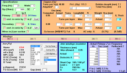
I've been playing with Yvesm's programme and this led me to this.

Which leads me to some questions...
- First one, obviously, does the design seem ok ? Could it be improved ?
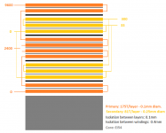
- Second one, is the practical implementation correct ? (see second pic attached)
- Third question, I found a seller of M6 laminations with reasonable prices in Italy: Lamierino da EI 30 a EI 120 - Italtras srl Has anyone experience with this webshop ? Or would rather suggest another source (in Europe) ?
- Fourth one, is this tape suitable for the isolation: Mylar adesivo ?
- Fifth and last one, has anyone a good source for bobbins and mounting hardware ? Italtras only has lams and wire.
Thanks a lot in advance for any comments on this 🙂
edit: this first post is out of date, please see the post 5
I'm considering to wind my own transformers for a parafeed output amp for headphones. What I'm looking for is :
- tapped secondary for 300r, 133r and 33r with a dual winding primary that can either be used in serie or // for around 10k or 2k5 input (about 6:1 or 3:1).
- decent inductance in order to be driven from rp as high as 3K (with 10K primary).
- lowish DCR for the secondary.
- able to fit in a 1U case. (40mm max)
The edcor PCW10K-7K/300-32 isn't too bad but the design choice for the primary doesn't suit me this time. The Carnhill vtb2291 is good but the ratio don't suit me either. The sowter 8665 is a bit expensive and the primary isn't good either.
I've been playing with Yvesm's programme and this led me to this.
Which leads me to some questions...
- First one, obviously, does the design seem ok ? Could it be improved ?
- Second one, is the practical implementation correct ? (see second pic attached)
- Third question, I found a seller of M6 laminations with reasonable prices in Italy: Lamierino da EI 30 a EI 120 - Italtras srl Has anyone experience with this webshop ? Or would rather suggest another source (in Europe) ?
- Fourth one, is this tape suitable for the isolation: Mylar adesivo ?
- Fifth and last one, has anyone a good source for bobbins and mounting hardware ? Italtras only has lams and wire.
Thanks a lot in advance for any comments on this 🙂
Attachments
Last edited:
Wow I envy you. This is too pro for me. I don't like my OTL headphone amp and I was thinking about output transformers but I have only wound some power transformers and it's a lot of work.... I was thinking of buying the Hammond's. You can look at the schematic here:
https://hollowstate.netfirms.com/manuals/OD300 Users Manual.pdf
https://hollowstate.netfirms.com/manuals/OD300 Users Manual.pdf
I don't like Your schem.....it is with and cap and OT in output....collored sound, IMO.Wow I envy you. This is too pro for me. I don't like my OTL headphone amp and I was thinking about output transformers but I have only wound some power transformers and it's a lot of work.... I was thinking of buying the Hammond's. You can look at the schematic here:
https://hollowstate.netfirms.com/manuals/OD300 Users Manual.pdf
I wound something similar to that on EI-85 cores that I salvaged from line transformers, but I only wound the 300R secondary. I think the EI-54 is going to be tight.
http://www.diyaudio.com/forums/tube...ng-interstage-transformer-24.html#post3813043
I tested the transformer with the proposed driver circuit (Mu-Stage 71A with FET on top)and it is flat from 5Hz to 100KHz with the exception of a slight (<0.5dB) hump around 10Hz.
For inter-winding insulation I used bamboo paper for model airplanes. I only used Mylar for outer covering.
I made bobbins from thick cardstock (manila folder) per directions in a book on winding transformers.
Coil Design and Construction Manual - Babani
Based on my transformers, I think your design looks good, but will be difficult on EI-54 cores.
Last edited:
Thanks a lot for the book suggestion, I'll have a look. I'll also read carefully the thread linked.
Such output transformers should run quite cool, I'll have a go at making my bobbins.
Wrt the core size. I can reduce a bit the number of turns if needed, based on the true dimensions of the bobbins,etc.. Inductance as it is should be quite high. To add to the confusion, the EI standard in Europe and in the US aren't the same; for the same number, a US core is significantly smaller. An European EI54 is barely smaller than an US EI75.
I've had a look at Yvesm transfo's winding schemes on his website and some others on the web. I also discussed by email with a custom transfo winder in France (I'll probably order the transfo finally... cost is reasonable compared to the work).
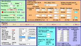
I thus modified things a lot. Since the smallest core commonly stocked by the winder is a EI60, I'll go for that. It allows me to use bigger wires. No more isolation in between layers but still in between sections.
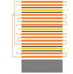
I attached the new design. I'd be glad if someone could check the winding connections. Primaries should be dual 2400R (9600R in serie), the secondaries can either be used as // for 33R or in serie for 300R.
Primaries are A-B and C-D, secondaries 1-2, 3-4, 5-6.
I thus modified things a lot. Since the smallest core commonly stocked by the winder is a EI60, I'll go for that. It allows me to use bigger wires. No more isolation in between layers but still in between sections.
I attached the new design. I'd be glad if someone could check the winding connections. Primaries should be dual 2400R (9600R in serie), the secondaries can either be used as // for 33R or in serie for 300R.
Primaries are A-B and C-D, secondaries 1-2, 3-4, 5-6.
Attachments
stupid. First there is no need for a 300 tap on a headphone transformer, 120 is what was always use stick with that for classic higher ohm phones, for the new low ohm phones 33 is a good choice.
the schematic, I agree with the previous poster. If you are using a transformer use a tube that doesn't need the cathode output, it will sound much better.
On a positive note I am very jealous of your ability to wind high nickle parafeed head transformers just aren't on the market, if you ever go commercial please contact me.
I've resorted to disassembling cheaper power transformers to wind my own transformer. Edcor actually does sell bobbins if you go to the parts section. The problem is that they are the american standard. Mable audio is the only other place where I have been able to find bobbins.
Others_MABLE AUDIO
Have you heard of Magnequest? His page seems it needs an update but I think he is still in business.
Magnequest Products - MQ Iron Listing/Pricing
Others_MABLE AUDIO
On a positive note I am very jealous of your ability to wind high nickle parafeed head transformers just aren't on the market, if you ever go commercial please contact me.
Have you heard of Magnequest? His page seems it needs an update but I think he is still in business.
Magnequest Products - MQ Iron Listing/Pricing
stupid. First there is no need for a 300 tap on a headphone transformer, 120 is what was always use stick with that for classic higher ohm phones, for the new low ohm phones 33 is a good choice.
the schematic, I agree with the previous poster. If you are using a transformer use a tube that doesn't need the cathode output, it will sound much better.
On a positive note I am very jealous of your ability to wind high nickle parafeed head transformers just aren't on the market, if you ever go commercial please contact me.
The question about stupid or not was only about the way the windings are arranged in the last config....
For the rest:
- My main headphones for the years to come are HD650 and K340. So I'd rather have a 300ohms taps than 120. Proper taps assure constant loading of the tube. With three secondaries (as on the sowter 8665), you can provide for 33, 133, 300 ohms taps.
- I don't plan to copy the mappletree ear, it was brought in the thread by Cassiel, not me. The idea of a 10k-2.4k primary is actually to have a transformer that could be used either from anode or cathode. To be completely heretical, I plan using one from a hybrid µ-follower (mosfet on top of a low µ tube).
- don't be jealous, my actual abilities are close to zero (winding a small power transformer or two doesn't count). I considered this project because it seemed like easy enough to start with audio transformers. I really don't intent to go commercial and might finally use a commercial winder. Did you ask electra-print ?
I've resorted to disassembling cheaper power transformers to wind my own transformer. Edcor actually does sell bobbins if you go to the parts section. The problem is that they are the american standard. Mable audio is the only other place where I have been able to find bobbins.
Others_MABLE AUDIO
In Europe, it seems that Asco will sell small quantities of bobbins and iron but not cheap.
ASCO Components - Transformer Laminations, Bobbins, Angles, Frames, Terminals and Enclosures.
Otherwise, this italian website has some bobbins and other hardware but no M6 iron in stock. It also starts at EI60.
http://www.enovaz.it/categorie-1665/Trasfo
In the first post, there's a link for another Italian website selling M6 lams.
And you could send an email to bobbinaudio to know where he sources his parts. transformateurs
I have CAD drawings of a lot of the bobbins I like and I might resort to 3D printing them.
It's weird how I can buy individual resistors and other basic electrical components but transformer parts seem to only be available in large volumes for professional transformer winders. Heck, even buying a transformer winder seems easier then getting bobbins and laminations.
It's weird how I can buy individual resistors and other basic electrical components but transformer parts seem to only be available in large volumes for professional transformer winders. Heck, even buying a transformer winder seems easier then getting bobbins and laminations.
The question about stupid or not was only about the way the windings are arranged in the last config....
For the rest:
- My main headphones for the years to come are HD650 and K340. So I'd rather have a 300ohms taps than 120. Proper taps assure constant loading of the tube. With three secondaries (as on the sowter 8665), you can provide for 33, 133, 300 ohms taps.
- I don't plan to copy the mappletree ear, it was brought in the thread by Cassiel, not me. The idea of a 10k-2.4k primary is actually to have a transformer that could be used either from anode or cathode. To be completely heretical, I plan using one from a hybrid µ-follower (mosfet on top of a low µ tube).
- don't be jealous, my actual abilities are close to zero (winding a small power transformer or two doesn't count). I considered this project because it seemed like easy enough to start with audio transformers. I really don't intent to go commercial and might finally use a commercial winder. Did you ask electra-print ?
No he asked if it was stupid or not and a trans for on a cathode follower is prettu stupid on a headphone amp imho, There is a great education at ecp audio.. I'm just being frank. We all come up with stupid ideas.
No he asked if it was stupid or not and a trans for on a cathode follower is prettu stupid on a headphone amp imho, There is a great education at ecp audio.. I'm just being frank. We all come up with stupid ideas.
Who is "he" ? I'm the only one to have use the word "stupid" and it was wrt post 5. The whole cathode follower stuff is an out topic in between Cassiel and azazzello. So could we please get the topic back on track ?
Topic is: how to best wind a transformer and more precisely, is the scheme of post 5 ok ?
Well at the risk of annoying 00940 further I have to explain myself. I already have a 6AS7 cathode follower but it distorts here and there with low impedance headphones. I thought transformers would be an easy fix for my problem. Those Hammond's fit inside the chassis. Regal says it's a stupid idea and that's OK - I had my suspicions too. So I'm satisfied know, I know what do with that amp - I'm getting my sledgehammer.
Now good luck with your questions 00940. Roger and out.
Now good luck with your questions 00940. Roger and out.
Ben,
I suggest you drop the multi tap configuration and start with a simpler single configuration with the 300R output and pick the primary to match your tube output.
My amp design is similar to yours in that I'm using a 71A Mu-Follower with a FET on top (Gyrator configuration)driving the parafeed transformer. The prototype works great and the FR exceeded my expectations. It both measures good and sounds good driving HD600s.
With the cores equivalent to an EI75 US, I think your stack-up is going to be tight the way you have it with multiple taps. If you look a the pictures in my thread, you will see that I had about 15% excess window area with US EI85 cores.
The first transformer I wound took up more of the window and I learned how to tighten the windings as I progressed. This is one reason I suggest you plan on winding a test transformer first. There is a learning curve to figure out how to wind the insulating paper and get it tight. With small transformers, I used thin light paper which tears easily. Learning to tension it and get it tight is a bit of a trick.
I tried Tissue paper but it was too flimsy.
@cassiel: don't worry, I'm not that annoyed. Just trying to make things clear. This said, the Mappletree Ear is reputed to be good sounding.
@TheGimp: thx for the comments and the (welcomed) warnings. I've been in touch with a guy in France doing custom jobs, the prices are more reasonable than I expected and I think I'll go with him. It will save me a lot of trouble. He doesn't seem worried about the space used by the copper so I'll trust him on that.
If I may ask, why use paper rather than mylar in between layers ? It seems the adhesive film would be easier to use.
No he asked if it was stupid or not and a trans for on a cathode follower is prettu stupid on a headphone amp imho, There is a great education at ecp audio.. I'm just being frank. We all come up with stupid ideas.
I'm the source? I have no problem with transformers after cathode followers. The step down transformer allows the phones to present the proper load to the tube.
but a literal 300 Ohms tap driving 300 Ohm headphones will give you a bass bump in the frequency response - most headphones today are designed, measured with low out Z amps, < 1/10 of the headphone Z
so if actual "hi fidelity", meeting published headphone frequency response curve is a goal then the xfmr should be designed for much lower output Z than the headphone
you can afford the impedance mismatch resulting low efficiency with most headphones - check the sensitivity numbers for yours - 100 mW into many 300 Ohm headphones will give near 120 dB SPL
without global feedback around the xfmr the only way to have effective damping ratio is to "mismatch" Zout and Zload, to "throw away" potential output
Last edited:
A 300 Ohm tap does not have an output impedance of 300 Ohms. A 300 Ohm tap is designed such that it reflects a 300 Ohm load on the secondary as the designed impedance to the primary. The actual output impedance will be the impedance of the tube's plate, reduced by the transformer's ratio, plus some copper losses, which will be considerably lower than 300 Ohms. For a reasonably designed transformer with a reasonable tube, it will likely be in the 40-50 Ohm range. Here, with the 3K tube, it might be more like 100-120 Ohms.
- Status
- Not open for further replies.
- Home
- Amplifiers
- Tubes / Valves
- Winding an output transformer for headphones ? Some questions