I just tried it again. From 6' away I can't see the cone move at all nor is there any sound. It shows 2.5V at switch on and takes about a full 10 seconds to settle to 1mV. These are JBL 4425 12" woofers that are pretty lively speakers so I don't think I will worry about it at all.
I just tried the Krypton-C and at turn on it flashes 3v for a split second and then drops instantly to 80MV. Something is not quite right there as it stays at about 65mv. I can't get my Krypton-V boards working so I can't test with those yet.
Blessings, Terry
I just tried the Krypton-C and at turn on it flashes 3v for a split second and then drops instantly to 80MV. Something is not quite right there as it stays at about 65mv. I can't get my Krypton-V boards working so I can't test with those yet.
Blessings, Terry
What's going on with the Kypton-V boards? Sounds like they aren't going down without a fight either.
Yes it would. Datalogging would be great as well. It would likely be inexpensive to build. Just need a talented coder.
Well, logging is not difficult to do. The point now is that it does not see which channel has triggered the sensor. It is possible to use a couple of analog inputs for measuring the voltage and recording it at pre-defined intervals...
I've got this functionality in my measurement system, so just did not bother implementing it in protection board initially 🙂
What's going on with the Kypton-V boards? Sounds like they aren't going down without a fight either.
Yeah, just haven't been able to get it yet. I hooked them up with 10R 5W resistors between PD and ND and the NFB so I would have something to measure across to set the current. One board will allow me to adjust it but the other won't. I tried hooking it up to an OPS and can't adjust the bias low enough so there is just something not right. I have been over the whole board and every resistor is correct. Each transistor test right with a diode test. I checked every trace and can't find any errors. I figure I'll just wait for Thimios to build his and see if his works. If so then I'll dig into it again. I don't want to bother everyone with trying to solve mine until I know it works.
Blessings, Terry
Does the Arduino have enough power to handle it or would a second one be required? Sounds like an interesting board to lay out.🙄
Yeah, just haven't been able to get it yet. I hooked them up with 10R 5W resistors between PD and ND and the NFB so I would have something to measure across to set the current. One board will allow me to adjust it but the other won't. I tried hooking it up to an OPS and can't adjust the bias low enough so there is just something not right. I have been over the whole board and every resistor is correct. Each transistor test right with a diode test. I checked every trace and can't find any errors. I figure I'll just wait for Thimios to build his and see if his works. If so then I'll dig into it again. I don't want to bother everyone with trying to solve mine until I know it works.
Blessings, Terry
You're taking all the fun out of it.
If I have time in the morning I will mark up a schematic with some voltages. It doesn't seem to have enough current. I think vbe for the KSAe1381/C3503 is only about .450. Not really enough to turn them on. Q5-Q8 are low as well.It might just need some resistor tweaks.
Does the Arduino have enough power to handle it or would a second one be required? Sounds like an interesting board to lay out.🙄
A board with an Arduino on it might take that 16 meg clock and reek havoc on the audio portion, so some Iso-Opto's are in order with a separate power supply and such. What has to be done will be done. So we will see. Computer chips are on a lot of commercial gear today, so it can be done, takes work and time. Something to do that is berry interesting to say the least.
Does the Arduino have enough power to handle it or would a second one be required? Sounds like an interesting board to lay out.🙄
More than enough. It's also got a hardware ADC onboard, so analog measurement is just a matter of reading the value from it - very quick. And it's a fast chip. A lot of potential... It can control a LED matrix or liquid chrystal screen in the backgroung, showing some graphs, parameters, texts - you name it. I did it for my video-transcoding equipment management 😉
A board with an Arduino on it might take that 16 meg clock and reek havoc on the audio portion, so some Iso-Opto's are in order with a separate power supply and such. What has to be done will be done. So we will see. Computer chips are on a lot of commercial gear today, so it can be done, takes work and time. Something to do that is berry interesting to say the least.
Even logging what is happening on the protection board would be helpful. Valery's got that pretty well isolated already. Adding some analogue 2 wire temp sensors to the heat sink would be nice. They're cheap enough to place on the transformer or other places as well. Monitoring rail voltages to see how much they droop, Inductive current sensing is easy and fairly accurate as well. Slipping a small gauge wire through the output inductor would likely do pretty well.
More than enough. It's also got a hardware ADC onboard, so analog measurement is just a matter of reading the value from it - very quick. And it's a fast chip. A lot of potential... It can control a LED matrix or liquid chrystal screen in the backgroung, showing some graphs, parameters, texts - you name it. I did it for my video-transcoding equipment management 😉
Yes, it is. My Led matrix using arduino.
Spooky at turn-on...
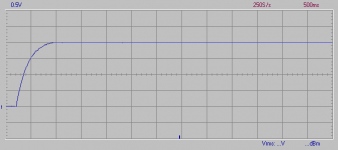
A quick shot of Spooky at turn-on. Note the change od vertical scale - the transient is much less pronounced, though similar in overall shape and time to settle. I can only assume at least partial cancellation from being a type of 'Complimentary Symmetry' architecture.
I'm tempted to simply pull a servo and see how it looks...
Attachments
Yeah, just haven't been able to get it yet. I hooked them up with 10R 5W resistors between PD and ND and the NFB so I would have something to measure across to set the current. One board will allow me to adjust it but the other won't. I tried hooking it up to an OPS and can't adjust the bias low enough so there is just something not right. I have been over the whole board and every resistor is correct. Each transistor test right with a diode test. I checked every trace and can't find any errors. I figure I'll just wait for Thimios to build his and see if his works. If so then I'll dig into it again. I don't want to bother everyone with trying to solve mine until I know it works.
Blessings, Terry
Either raise R20 to 56R-68R or raise R27/R35 to 180R , this will lower VAS I.
Pick the one that will be the closest desired current
for the trimmer (R21) , to be equal to 50R (1/2 way).
OS
A quick shot of Spooky at turn-on. Note the change od vertical scale - the transient is much less pronounced, though similar in overall shape and time to settle. I can only assume at least partial cancellation from being a type of 'Complimentary Symmetry' architecture.
I'm tempted to simply pull a servo and see how it looks...
Pulling the servo would let you know if it's originating there or somewhere else.
A quick shot of Spooky at turn-on. Note the change od vertical scale - the transient is much less pronounced, though similar in overall shape and time to settle. I can only assume at least partial cancellation from being a type of 'Complimentary Symmetry' architecture.
I'm tempted to simply pull a servo and see how it looks...
Ahha... familiar Velleman PCSU screen 🙂 I've got the same device...
Servo-less
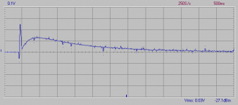
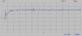
Two quick shots of both Symasui and Spooky without the servo. Symasui is the one that ends up with 2V offset and Spooky only 200mV. It looks like the more extreme settling behaviour is the result of a much larger offset for the servo to deal with. I suspect if Symasui's offset can be minimized without the servo then the behavior will improve.
Two quick shots of both Symasui and Spooky without the servo. Symasui is the one that ends up with 2V offset and Spooky only 200mV. It looks like the more extreme settling behaviour is the result of a much larger offset for the servo to deal with. I suspect if Symasui's offset can be minimized without the servo then the behavior will improve.
Attachments
Ahha... familiar Velleman PCSU screen 🙂 I've got the same device...
Mine just arrived last week.
Two quick shots of both Symasui and Spooky without the servo. Symasui is the one that ends up with 2V offset and Spooky only 200mV. It looks like the more extreme settling behaviour is the result of a much larger offset for the servo to deal with. I suspect if Symasui's offset can be minimized without the servo then the behavior will improve.
Would the settling be a slow charging cap?
I've been trying to deal with similar DC servo issues. The settling (as opposed to a 'gliding' slope) is because the time constant of the DC servo input filter is larger than the time constant of the integrator. If you swap the time constants to make that of the integrator greater, it stops ringing and becomes gliding. But a decent filtered/integrated servo takes so long to settle 🙁
- Home
- Amplifiers
- Solid State
- Slewmaster - CFA vs. VFA "Rumble"