I've recently acquired a "few" (6 to be exact) AV123 Monoblock X-Amps, and since the price I got was quite good, I decided to buy enough for a tri-amp setup. The internal photos definitely does not look impressive at all, but the price is right, and the circuit appears to be near exact copy of the reference circuit. Which saves me the trouble of tracing and find out what exactly each item is doing.
First of all, I'd like to say it doesn't sound as good as the reviews I've been seeing, and nor does my copy have any hiss or hums. I find the amp is unable to produce a LOT of the finer details that even a Yamaha consumer integrated amp can do easily (It's a pretty good Yamaha amp, but still a consumer grade integrated amp, not anywhere audiophile at all).
As I'm a true modder at heart, I opened it up, and double checked a few infos on the net, and looked up the datasheet (http://www.nxp.com/documents/data_sheet/TDA8920B.pdf). What I found tells me that this amp, at least the Class D amp part does not seem to be designed by audiophile, but just your average consumer electronics OEM. There is no tweak whatsoever, and the signal pass through not one capacitor, but two. One at the input buffer board, one at the main amp board. The sad part is that this circuit doesn't need any coupling caps, it will work perfectly fine with all those caps shorted. Which vastly improves the sound quality.
The output filter according to datasheet is setup for 2Ohm speakers, which I've been warned that this circuit will not be able to work well with when it is setup as BTL (which is what these monoblocks are).
The good part about these amps is that the layout seems pretty decent, and since it is pretty much reference circuit, it means it can be modded into a true balanced input monoblock as well. Which is just perfect for me, and I intend to do so sometime down the road.
Here's what I've done so far:
REMOVE & SHORT:
(Main Amp PCB) C1, C2, C16, C17 (Tested, working fine and better detail)
(Buffer PCB) C49 (Modded, not yet tested)
What I plan to do:
Change output filter to 22nH & 680nF as per datasheet's 4Ohm single ended setting (which should translate into 8Ohm @ BTL)
Change all caps to something better than Jamicon and no brands
Upgrade speaker wire hook up and binding post
Upgrade U2/U3 on main PCB to TO-220 version of the regulator, and up it to 15V instead of 12V
Either upgrade the buffer op amp (ST TL072) or perhaps ditching it completely.
(Maybe a long time later) Upgrade it to true balanced input, maybe keeping the buffer or maybe not.
Anyone still hanging on to these puppies? I do have other pretty good sounding amp with a lot more power (with Hitachi MOSFET and 280W per channel of old fashioned Class AB power), but these puppies are just so much smaller and easier to fit into smaller living room.
I have TDA8950th based amps from connexelectronics. I also think thay a close to recommendations from NXP. Right now they are refitted in to new enclosures.
I have used them for subwoofer duty, and here they do very well. I have also used them full range. They do nothing special in midrange and tweeter. I would rather use my Panasonic SA-XR55 with spdif input as mid/high amplifier. I really don't need anything better in this region, but the SA-XR55 lacks some quality in the woofer region.
I have used them for subwoofer duty, and here they do very well. I have also used them full range. They do nothing special in midrange and tweeter. I would rather use my Panasonic SA-XR55 with spdif input as mid/high amplifier. I really don't need anything better in this region, but the SA-XR55 lacks some quality in the woofer region.
I have TDA8950th based amps from connexelectronics. I also think thay a close to recommendations from NXP. Right now they are refitted in to new enclosures.
I have used them for subwoofer duty, and here they do very well. I have also used them full range. They do nothing special in midrange and tweeter. I would rather use my Panasonic SA-XR55 with spdif input as mid/high amplifier. I really don't need anything better in this region, but the SA-XR55 lacks some quality in the woofer region.
I think partly the problem is due to the reference circuit is VERY safe, it is guarding against problems that almost never materialize. Like coupling capacitor is to guard against DC bias, which does not exist in this amp, and nor does my pre-amp sends out signal with any significant DC bias. I couldn't foresee how such event can happen, and yes, if my pre blow up, it could do that, but I don't see how that could have happen in such a disastrous way.
Kinda like those voltage adjust pots on circuits that only need ONE fixed voltage, they put it on there so that you can "adjust" them if they ever drifted. Well... that never happened either, what is more likely to happen is the pot degrade and cause problem. A pair of cheap resistors in this case is much better, and simply ignore a problem that never needs fixing. 😉
I'm taking a closer look at the output filter of the thingy, normally one would assume that most user have 8 Ohm speakers, but this setup for 2 Ohm speaker in single ended setting. I assume that would roughly equal to 4 Ohm for BTL. Which is why I'm thinking about replacing the 1uF filter cap with 680n ones (which is for SE 4 Ohm speaker setup, and BTL I'm thinking it would be for 8 ohm speaker).
As for the other part of the filter, the inductor is not marked, and I plan to change that to 22uH to match the recommendation in their datasheet.
This is what I plan to do anyways, anyone got any idea on the inductor and capacitor value?
As for the other part of the filter, the inductor is not marked, and I plan to change that to 22uH to match the recommendation in their datasheet.
This is what I plan to do anyways, anyone got any idea on the inductor and capacitor value?
Well, I got a bit of time today and dug up the amp for some more mods... I looked over the caps that I plan on swapping, and found that there are tons of 47uF/63V caps, and most of them are on 28V power rails. IMHO they just get ONE 47uF cap, rated at 63V, instead of at different ratings. This eases inventory management, and you get one part that can be used anywhere that needs 47uF cap.
C33/35 470uF/35V = Appears to be the cap for 1st stage LC filtering, swapped a 10% larger NCC KY cap in. (28V circuit)
C37/38 47uF/63V = the second stage LC filtering and main amp bypass, swapped in 47uF/35V Elna Silmic II instead (28V circuit)
C39 1uF/63V = first part of the first stage LC filtering, swapped this no name yellow film cap out and swapped in a ERO 2.2uF/63V MKT cap in. Not all MKT sounds nice, but ERO does it pretty well.
C41/42 47uF/63V = also the second stage LC, but feeding to a regulator to drop it to +/- 12V, also swapped in 47uF/35V Elna Silmic II instead (28V circuit)
C43/44 47uF/63V = output cap of the LM78L12/79L12, I see absolutely no point having a huge cap here, swapped in 10uf/35V Elna Silmic II instead (12V circuit)
(on input buffer board)
C53/56 = SMD ceramic cap of unknown value, I prefer to have some kind of reserve in bypass caps after the power had gone through a jumper cable, since I got no convenient place to install them, I just soldered two 10uF/35V Elna Silmic II cap on top of the ceramic caps. (12V circuit)
(didn't touch)
C36 47uF/63V = this cap is placed across the positive and negative rail, thus the potential is about 56V, I don't have anything on hand that would tolerate the voltage and fit the position, thus I'm leaving it alone for now.
If I'm to categorize the mod in stages:
Stage I
Signal path capacitor removal/short circuit C1/C2/C16/C17/C49
Stage II
Swapping LC filter and bypass cap for the amp chip C33/C35/C37/C38/C39
Stage III
Adding ely bypass to input buffer board (solder on top of C53/C56)
Stage IV
Swapping out LC and output cap for the LM78L12/LM79L12 C41/C42/C43/C44
(Below is still not done yet)
Swapping out LM78L12/LM79L12 with big-o TO-220 version of LM7815/LM7915 with heatsink.
Find some proper LC parts for amp's output filter
Find a nice 63V or higher ely cap to replace C36
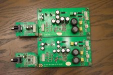
the photo below is one PCB at Stage IV(top) and one at stage I(bottom)...
The amp chip is at the bottom, but most of the easily modded parts are on top. 🙂
The crud on the PCB are rosin (I hope), if you didn't wash them off completely and they go in contact with water, they will turn into whitish crud coating your PCB... I think the OEM didn't pay their worker enough to have it cleaned spotless.
Attachments
Last edited:
Capacitor upgrades appears to have produced a much bigger result than the coupling removal. I tested not with music but with TV shows, as it was like midnight and I couldn't reasonably turn it up without ******* off someone 😉....
I have found that the more detail there are, the lower I will be able to turn my volume. With crap setup, I often have to turn it up quite a bit to understand what they were speaking. With good setup, I can hear a lot of detail, even at very low volume. (which is a good thing a night) I'll see what it can do with music later on.
I have found that the more detail there are, the lower I will be able to turn my volume. With crap setup, I often have to turn it up quite a bit to understand what they were speaking. With good setup, I can hear a lot of detail, even at very low volume. (which is a good thing a night) I'll see what it can do with music later on.
- Status
- Not open for further replies.
- Home
- Amplifiers
- Class D
- AV123 X-Amp modding...