So, how big could you make one and it still be effective?
Could you 'do' 150Hz with a larger driver?
Could you combine drivers (by putting them next to each other) to get the most bandwidth possible?
Could this be used with a standard horn flare to reduce the overall length?
Could you 'do' 150Hz with a larger driver?
Could you combine drivers (by putting them next to each other) to get the most bandwidth possible?
Could this be used with a standard horn flare to reduce the overall length?
So, how big could you make one and it still be effective?
Could you 'do' 150Hz with a larger driver?
Could you combine drivers (by putting them next to each other) to get the most bandwidth possible?
Could this be used with a standard horn flare to reduce the overall length?
It's just a horn folding scheme, no more, no less
You can put whatever driver on it that you want
If anything, I think it's better suited for midrange and lower midrange, where diffraction is less audible.
You could make an interesting speaker by putting a high efficiency 8" in a Paraline and then using a direct radiator tweeter array, similar to the CBT arrays that JBL sells
It sounds like the concept is 'simple', which is usually a good thing!
Well, I have an Eminence Alpha 8a, which isn't the most sensitive in the world, but still up there. As for the direct radiating tweeters, I have a few options that I can at least experiment with.
I'm trying to follow your idea through, so for the 8" Paraline, what dimensions would I need?
I ask in layman's terms so that if something pans out, other people can understand me 🙂
It sounds like the concept is 'simple', which is usually a good thing!
Well, I have an Eminence Alpha 8a, which isn't the most sensitive in the world, but still up there. As for the direct radiating tweeters, I have a few options that I can at least experiment with.
I'm trying to follow your idea through, so for the 8" Paraline, what dimensions would I need?
I ask in layman's terms so that if something pans out, other people can understand me 🙂
It's just a radial horn with a 180 degree bend in it
So the mouth of the horn is the same as the area of the perimeter of a cylinder, IE it's :
2 * pi * r * height
The length of the horn is equal to the radius.
You can figure out the area of the points in between the throat and the mouth using the same formula as the horn mouth.
Easiest way to sim it by far is to make a spreadsheet, so that you can plug in a height and a depth and spit out every point in between.
If there is a 180 deg fold, isn't the length of the horn equal to 2x the radius (from entrance to edge of eye shaped slot)?
I just wanted to make sure I understand, and I ended up thinking in a slightly different way, hence the need for clarification 🙄
I'll use metric units:
150Hz = roughly 229cm
I assumed that this would refer to a quarter of a circle's path (90 degrees), and after a little bit of dividing, the radius of the full circle would be about 1.46 metres.
So, in conclusion, we would make a 90 degree reflector that had a radius of 1.46 metres.
That only takes care of the 'cross section' of the cylinder. The length of the cylinder I'm unsure of how to calculate.
I just wanted to make sure I understand, and I ended up thinking in a slightly different way, hence the need for clarification 🙄
I'll use metric units:
150Hz = roughly 229cm
I assumed that this would refer to a quarter of a circle's path (90 degrees), and after a little bit of dividing, the radius of the full circle would be about 1.46 metres.
So, in conclusion, we would make a 90 degree reflector that had a radius of 1.46 metres.
That only takes care of the 'cross section' of the cylinder. The length of the cylinder I'm unsure of how to calculate.
? I'm confused ? Maybe a sketch would be helpful.
If there is a 180 deg fold, isn't the length of the horn equal to 2x the radius (from entrance to edge of eye shaped slot)?
When I say "radius" I mean the radius before the horn is folded. An 8"x4" tall Paraline has a path length of 4".
? I'm confused ? Maybe a sketch would be helpful.
Something like this?
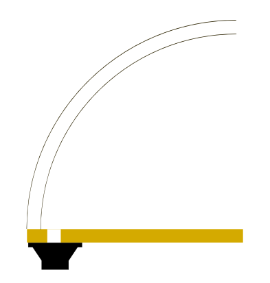
When I say "radius" I mean the radius before the horn is folded. An 8"x4" tall Paraline has a path length of 4".
Still confused because a Paraline has two parabolas and a radius implies a circle. I know you had a "squaraline" earlier where you had 4 folds around a circle but we are talking about different things I think. Again, maybe a sketch would be helpful.
You may want to think about the why, for that. Is there a problem with midbass radiation patterns you are trying to solve?Something like this?
Not immediately, but considering that I've caused confusion means that I've misunderstood.
That was my guess at what a 150Hz lens would look like, but I'm guessing that it's more a case of putting the 8" driver through the Paraline, and then using a smaller lens.
I'm probably wrong on that assumption too, so I'm going to step back and let the clever people come to a conclusion, because all I'm doing is messing things up.
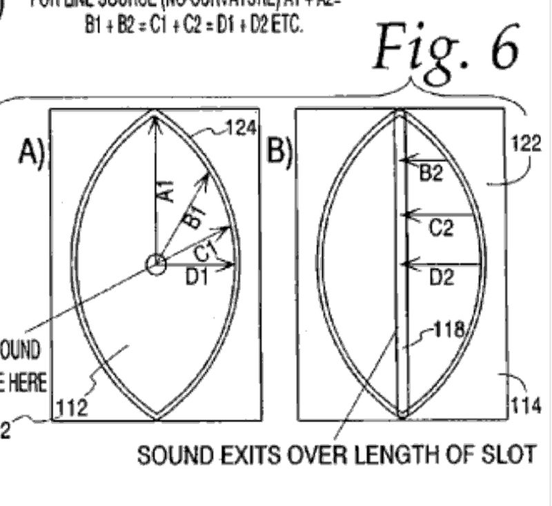
Unfold a Paraline. You get a circle. That's how it works. That's how it keeps the wave front in-phase.
The radius of the circle is the same as the distance from the center of the Paraline to the top of the Paraline.
The circular distance once unfolded is also one of two correctable reasons
why the default line source timing of paraline makes for ragged response.
Distance from driver to exit slot is the same via any ray properly traced.
Both its greatest feature and its greatest flaw...
A huge discontinuity from thin waveguide to 180 degree dispersion reflects
back at the driver! The second thing reflecting back at the driver is the middle
of the mirror (from center to oh-say about C1 in your drawing). The portion
of the parabola that is within an eighth wave of scribing a circular arc around
the driver, might as well be a circular arc for the problem it creates. And thats
exactly half the distance of the exit slot problem, further reinforcing the same
dips and peaks.
The Smith Cassegrain experiment is meant to do away with all but a tiny bit
of the mirror and exit slot reflecting directly and coherently back at the driver.
Present a somewhat less drastic change of expansion rate at the mirror and
hugely less drastic change at the exit slot roundover. The distance and time
to each of these known discontinuities purposely approached at an angle.
And a bit of directly-on-vertical-axis treble boost between the roundovers,
though I have no idea how much that effect will offset the losses due to
wide horizontal constant directivity.
---
@Una: Something like that, but your driver is drawn a little too close to the
back wall of the lens. You need to draw a half parabola rather than a circular
arc, and be in the focus point.
Last edited:
Everything you say is true.
But the SAW lens is also an elegant solution.

A 1" compression driver on a SAW lens has vertical directivity dictated by the plates above and below it. Above 13,500khz, it's beamwidth is narrow like a Paraline.
Basically a SAW lens can do everything a Paraline can do, with less diffraction, as long as you can live with a single driver.
But the SAW lens is also an elegant solution.
A 1" compression driver on a SAW lens has vertical directivity dictated by the plates above and below it. Above 13,500khz, it's beamwidth is narrow like a Paraline.
Basically a SAW lens can do everything a Paraline can do, with less diffraction, as long as you can live with a single driver.
How did stargate measure? Its got the pseudo-circular mirror center,
rough woodgrain, and midrange holes working against it. But on the
other hand, the exit discontinuity is smeared at an angle and rounded.
rough woodgrain, and midrange holes working against it. But on the
other hand, the exit discontinuity is smeared at an angle and rounded.
The problem with a Stargate is that the volume is half as much as a Paraline with the same passband. (Because it's half the size.) I'd expected that it wouldn't work, but it basically measured the same. On the down side, my measurement was with an RTA.
I couldn't decide which sounded better.
I couldn't decide which sounded better.
If there is a 180 deg fold, isn't the length of the horn equal to 2x the radius (from entrance to edge of eye shaped slot)?
Yes, thats the distance from the driver to the exit discontinuity.
But is that the distance of the horn?
The case of paraline is a little confusing because it only expands
on the backside. There is no hornlike expansion on the frontside
of the fold. The rays (if properly focused) are intentionally parallel.
And then it expands again violently when it leaves the exit slot.
So its like horn, no horn, horn again, go figure...
Everything you say is true.
But the SAW lens is also an elegant solution.
A 1" compression driver on a SAW lens has vertical directivity dictated by the plates above and below it. Above 13,500khz, it's beamwidth is narrow like a Paraline.
Basically a SAW lens can do everything a Paraline can do, with less diffraction, as long as you can live with a single driver.
Is there a way to combine drivers to fire from a single exit, without using a Paraline, seeing as the lens covers the dispersion patterns?
Is there a way to combine drivers to fire from a single exit, without using a Paraline, seeing as the lens covers the dispersion patterns?
Sure, same way you do it in a Synergy horn:

In that picture from Danley's patent, you're looking down the throat of a Synergy horn.
To do it with a SAW lens, you'd be looking at it from overhead:
Tweeter in the center, surrounded by midranges, which are surrounded by woofers.
- Home
- Loudspeakers
- Multi-Way
- Square Pegs