I think Ive found the problem Mooly? Its either the stereo mono switch or a cold solder joint on it be cause I just grounded it and I got stereo.Thanks for solving this for me mate. Its a really good tuner in fact its the best Ive heard Im rapt.Yay!
Last edited:
🙂
Or the oscillator pull in range needs tweaking. See if you can get it 100% working first and then we can have another look why its behaving like it is.
Edit... hadn't turned the page. Yay ! lol. That's great... working 😀
What we could look at next is disconnecting the feed to pin 16. I've not got the circuit on this PC but if you trace pin 16 back you'll see it goes to a couple of diodes and a resistive ??? feed from somewhere. The diodes mean that pin 16 can not be pulled low from those points, but it might be being taken high by a problem from them. Measuring and isolating those feeds might give a clue. Of course it could just be possible it is a chip problem but its still not the first suspect. Only when everything that connects to pin 16 has been investigated and proved not to be the reason for the pin not being near zero do we suspect the IC.
Edit Edit... do you mean you grounded the switch and got stereo ? or just grounded the IC pin ? If the switch then definitely sounds like a problem in that area.
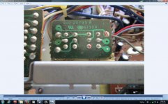
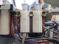
Heres some photos Mooly,the gray wire must be the grounding wire? I could see on the solder side when I had it apart where someone had re soldered all the wires coming from the power and stereo,mono,narrow band etc...switches
Attachments
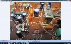

The first photo with the grey wire is wrong its the bottom grey one that goes to pin 16.Sorry about that chief! I found that there is only an 820k ohm resistor between the stereo-mono switch and pin 16 with my DMM. Remember that I replaced the two 2SC1815 transistors at the output of the tuner, I wonder if that has anything to do with it? The stereo-mono switch appears to be working, at least it is when I have my DMM on continuity on the marked pins?
Attachments
Last edited:
Not easy to follow is it, and not easy on an on screen diagram compared to a paper pull out manual.
There's a lot going on in terms of diode gating around that chip.
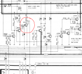
Lets keep it simple for now. With pin 16 pulled low we say it works OK in stereo. Is that still correct ? If so then look at Q403 that drives the Quartz Lock bulb.
Is the bulb lit or not ?
If not then remove the short from pin 16 and instead short Q403 from collector to emitter. The bulb should light. Does it work in stereo now ? It looks like that bulb has to be lit to pull pin 16 down via the 82k (R407).
There's a lot going on in terms of diode gating around that chip.
Lets keep it simple for now. With pin 16 pulled low we say it works OK in stereo. Is that still correct ? If so then look at Q403 that drives the Quartz Lock bulb.
Is the bulb lit or not ?
If not then remove the short from pin 16 and instead short Q403 from collector to emitter. The bulb should light. Does it work in stereo now ? It looks like that bulb has to be lit to pull pin 16 down via the 82k (R407).
Attachments
Not easy to follow is it, and not easy on an on screen diagram compared to a paper pull out manual.
There's a lot going on in terms of diode gating around that chip.
Lets keep it simple for now. With pin 16 pulled low we say it works OK in stereo. Is that still correct ? If so then look at Q403 that drives the Quartz Lock bulb.
Is the bulb lit or not ?
If not then remove the short from pin 16 and instead short Q403 from collector to emitter. The bulb should light. Does it work in stereo now ? It looks like that bulb has to be lit to pull pin 16 down via the 82k (R407).
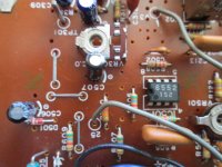
Yes the Quartz lock bulb is working. Ive got the tuner apart at the moment, Ive been trying to follow the circuit around.The only thing I can find ""wrong"" is a diode that reads 0.09 both ways but it is in parallel with an RF transformer? The pin 16 line branches off to one of the quartz lock light wires thru a 100k ohm resistor that's gone high to 115.4k so Ill change that out.
Last edited:
Remember you can't read components accurately in circuit. I'd be very wary of altering anything in the RF stages.
Remember you can't read components accurately in circuit. I'd be very wary of altering anything in the RF stages.
I went to change that 100k resistor and it turned out to be 120k? So it hadn't gone high at all, I was measuring from the solder side and and trying to line them up on the other side to follow the circuit at the same time and looked at the one next to it.(that's my story and I'm sticking to it) Ha! What if I just solder pin 16 to ground and be done with it because Ive got a feeling that when the 2 output transistors Q602 & Q603 failed they stuffed up the stereo decoder chip with it.It looks to me that someone has plugged the outputs into something they shouldn't have and burnt them out? Ive spent all day looking and testing components and cant find anything wrong? So it must be that bung chip? What do you think Mooly?
What do I think 😛
If those transistors were zapped then that does suggest something has happened. Yes you can just short pin 16 if it all works OK
One last thing to try if you can do this. Isolate pin 16 (you might need the cap there though) and see if the voltage on pin 16 falls to zero. If it does then the problem is not the chip, its something feeding into pin 16. If it doesn't fall to zero then there could be internal leakage in the chip.
What do I think 😛
If those transistors were zapped then that does suggest something has happened. Yes you can just short pin 16 if it all works OK
One last thing to try if you can do this. Isolate pin 16 (you might need the cap there though) and see if the voltage on pin 16 falls to zero. If it does then the problem is not the chip, its something feeding into pin 16. If it doesn't fall to zero then there could be internal leakage in the chip.
How do I do this? Do I use a DMM ?what cap do you mean the one off of pin 16 itself?
Last edited:
If I were doing it I'd use braid to cleanly unsolder pin 16 (so the pin is free from the print) and then add a similar cap carefully from the pin itself to ground. The value of the cap isn't critical... you could try without.
Then just see if it works in stereo and also check the DC voltage directly on the isolated pin.
Another quick and dirty way. Just use a craft knife to nick the print and isolate it.
Then just see if it works in stereo and also check the DC voltage directly on the isolated pin.
Another quick and dirty way. Just use a craft knife to nick the print and isolate it.
I'm going to just solder it to ground because its just too much stuffing around taking it apart again and hassling around to try and earth it somehow while I isolate the pin.I can see me shorting something out otherwise.As long as it works in stereo that's all I ask,so thanks for getting it going for me Mooly its really appreciated. I thought my Pioneer TX410 was not a bad tuner Ive been listening to it today but this Technics is heads and shoulders better.
No problem and your very welcome 🙂
Its been good to revisit the theory on FM tuners and put it all into practice again.
Its been good to revisit the theory on FM tuners and put it all into practice again.
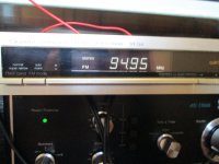
Ive got it going now and it sounds great. I didn't think a tuner could sound this good,its amazing. I soldered the ground line to the 820k resistor instead of taking the chance of cooking the chip.Ive got a bit of a hum on one station 94.90mhz,all the rest are OK. Can I tweak that hum out? I can just hear it at a low volume but it gets louder as I increase the volume.
False alarm! The hum was only there for a little while and now its gone it must have been some interference from somewhere?
- Status
- Not open for further replies.
- Home
- Source & Line
- Digital Source
- Technics ST-S4