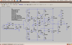
Esperado put forth a VSSA variant that was DC coupled (intended to make use of a DC servo) by using a diamond buffer input. I know some don't like the diamond buffer due to some concerns about stability but in this example it seems to work out pretty well. I couldn't get the distortion to simulate as low as Esperado but I'm intrigued by the possibility of DC coupling, especially eliminating the split NFB paths and big DC blocking capacitors.
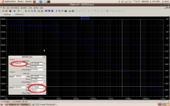
I started just playing around with it and found I could get some pretty good PM and GM with some (rather large values of) lead compensation. I need to bring into to simulation realistic CCSs and bias spreader to make it a more complete circuit, but this give a little hint of what it might be like.
Thoughts?
Attachments

How about a quick prototype with simple ccs and bias spreader. Let's see how good the actual offset is and of course, the sound...
Yes, I just wanted to see basic performance, offset notwithstanding. A real build may or may not need a DC servo, but of course a servo makes offset a non-issue. For the basic simulation the servo was an unnecessary complication.
Last edited:
R1, R2 are meaningless, R9, R10 too large, C8 dangerous, Q1, Q4 buffer could degrade SQ. At the end all comes down to implementation, choice of parts, etc.
R1, R2 - R in series with respective current source isolates the active devices from C in the current sources. Right?
Last edited:
R1, R2 - R in series with respective current source isolates the active devices from C in the current sources. Right?
Usually, these resistors are in series with the emitter of Q1, Q4.
Their purpose is to provide a bias for Q2, Q5 and to set the quiescent current of these transistors which receive the negative feedback on their emitter.
Even if R1, R2 were in the right position, I am not sure of a stable DC behavior of the circuit.
I just drew the circuit as presented by Esperado, minus the DC servo which in real life would almost certainly be included, and with lead comp (C8) added. LC said C8 was dangerous, and it might be, but in the simple simulation it gained me more PM and didn't compromise GM.
As for the TSSA, I've looked and it isn't so simple. The original premise might be, but the implementation as presented is quite complex. Plus I'm not after a commercial module.
As for the TSSA, I've looked and it isn't so simple. The original premise might be, but the implementation as presented is quite complex. Plus I'm not after a commercial module.
LC said C8 was dangerous, and it might be, but in the simple simulation it gained me more PM and didn't compromise GM.
Would agree with LC on this one. Having messed around with various CFA prototypes, have found that too large a value in position C8 can cause instability / oscillation. Putting a resistor in series with C8 may help keep things stable.
Usually, these resistors are in series with the emitter of Q1, Q4.
Their purpose is to provide a bias for Q2, Q5 and to set the quiescent current of these transistors which receive the negative feedback on their emitter.
Even if R1, R2 were in the right position, I am not sure of a stable DC behavior of the circuit.
Hi forr,
I meant R1, R2 in series with the CCS intrinsic capacitance. These resistors will not alter standing currents.

But, these resistors will dampen the Q. I think John Curl wrote somewhere "making the CCS less hot".
But, these resistors will dampen the Q. I think John Curl wrote somewhere "making the CCS less hot".
R1, R2 will drop 75 mV, in series with several M Ohms of CCS impedance will do exactly nothing.
Me learnt a lot in this SSA, TSSA, VSSA & First One journey, all knowledge to get really good sound concentrated in FO v1.3., some tricks not seen in any threads, especially not combined together, trade secrets I could say.
L.C.

R1, R2 will drop 75 mV, in series with several M Ohms of CCS impedance will do exactly nothing.
L.C.
I did mot choose resistor value. I just speculated about one possible reason for those resistors.
Esperado, can you explain why these resistors and chosen value?
Last edited:
Would agree with LC on this one. Having messed around with various CFA prototypes, have found that too large a value in position C8 can cause instability / oscillation. Putting a resistor in series with C8 may help keep things stable.
Gain and PM "peaking" right at the UG point. I don't use this for my CFA's , but on my hawksford/leach ... I use 100R/5p. Being a VFA (only need 5P) , this allows for more PM @ higher UG's (as JK observed).
PS - the observed "peaking" made a high slew SW "ring" 🙁 .
OS
DVSSA Simulation
Today I played around with DVSSA in simulator. Here are some conclusions:
1) The diamond buffer will surely improve bass, which is often "weak" with LATFET.
2) Most CFA have terrible transition from class-A to class-B and in general the performance at higher power is not as good as at lower power. But the diamond buffer will make good performance up to maximum power.
3) At low power the quality is still better without diamond UNLESS extra transistor is added for the input transistor (not buffer) that acts as a current source.
4) The input stage must be run hot (Esperado runs 3.8mA) for best performance but then servo is mandatory. With lower current the servo is not needed. Emitter resistors (with the input and buffer transistors) may help when current gets bigger.
So till here, I will only add the diamond buffer for bass amp in a multi-amp system or in a high power amp but then I have to add the extra transistor I mentioned in point#3.
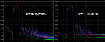
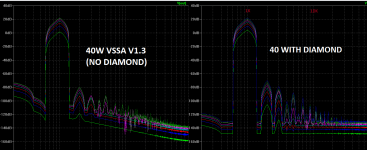
FFT images are useless, if shown only one, because what we need to see is the relative differences between circuits. Below are 2 FFT charts. The first one is without the diamond buffer, the second one with the diamond added (but no other extra transistors). The last curve represents an output of 40W (Clipping at 45W).
I think I will use the diamond buffer (with extra transistor) for my high power CFA. It is much better than what I can achieve with Slewmaster IPS!!
Today I played around with DVSSA in simulator. Here are some conclusions:
1) The diamond buffer will surely improve bass, which is often "weak" with LATFET.
2) Most CFA have terrible transition from class-A to class-B and in general the performance at higher power is not as good as at lower power. But the diamond buffer will make good performance up to maximum power.
3) At low power the quality is still better without diamond UNLESS extra transistor is added for the input transistor (not buffer) that acts as a current source.
4) The input stage must be run hot (Esperado runs 3.8mA) for best performance but then servo is mandatory. With lower current the servo is not needed. Emitter resistors (with the input and buffer transistors) may help when current gets bigger.
So till here, I will only add the diamond buffer for bass amp in a multi-amp system or in a high power amp but then I have to add the extra transistor I mentioned in point#3.
FFT images are useless, if shown only one, because what we need to see is the relative differences between circuits. Below are 2 FFT charts. The first one is without the diamond buffer, the second one with the diamond added (but no other extra transistors). The last curve represents an output of 40W (Clipping at 45W).
I think I will use the diamond buffer (with extra transistor) for my high power CFA. It is much better than what I can achieve with Slewmaster IPS!!
Attachments
Last edited:
In case you are familiar with VSSA V1.3 then here is how it looks like in my simulation, compared with the previous DVSSA.
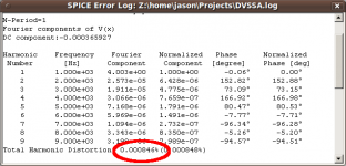
Please note that it is easy to get sub-ppm distortion with DVSSA if we compromise other qualities. The DVSSA here is not so good because it has to match VSSA quality in other area. But for most people (and average system situation) I believe DVSSA is preferable.
Please note that it is easy to get sub-ppm distortion with DVSSA if we compromise other qualities. The DVSSA here is not so good because it has to match VSSA quality in other area. But for most people (and average system situation) I believe DVSSA is preferable.
Attachments
I think I will use the diamond buffer (with extra transistor) for my high power CFA. It is much better than what I can achieve with Slewmaster IPS!!
Just putting diamond buffer alone as input stage in VSSA will not do miracles, more important is its practical implementation, which has to be flawless, meaning using very good CCS, ...
As nowadays people expected the output DC offset to be in a range of +/-0,1 mV, DC servo would also be needed.
In Slewmaster CFA series there are some details which are technically speaking electrically correct solutions but not as good as needed to be to achieve better sound.
At the end, as always, all is in details.
- Status
- Not open for further replies.
- Home
- Amplifiers
- Solid State
- Evolution of the VSSA? Esperado's DVSSA...