Yes, capacitors are the reason I didnt want to inject DC into the signal. With big enough transformer you could do that if the transformer is on the output of the ldrs.
Uriah
Uriah
Member
Joined 2009
Paid Member
My idea allows for the construction of multi-channel LDR attentuators without having to match any LDRs - but that would get expensive quickly if it required several high performance transformers. Capacitors is the only option for the idea I had.
Well you should build it. Dont let me or George make you feel you shouldn't. It'll still sound good. Maybe not as great as not cap but good is good.
Hi,
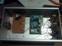
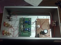
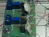
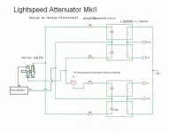
Was hoping someone could help me with this project. I didn't have the schematic for the board, so I used the basic schematic by George found online and in the thread.
The board says Design and layout Uriah Daily 2009.
I'm getting some audio from channel 2, but only hum from channel 1.
Think I might have the optocouplers in wrong.
Using 100 ohm for resistors and 5k pots. Volume adjustment is 100k.
Using 12v walwart and regulated down to 5v.
If I turn volume up all the way get audio from 1ch that's low but not distorted.
Other channel is just him.
Thanks for any advise or proper schematic would be helpful too.
Vince
Attachments
Last edited:
Vince
I cant attach the file as its a few Kb larger than allowed.
Okay, linked pdf manual here:
https://drive.google.com/file/d/0B0N-dmOQiKmAYTZmMDdjNDUtZTkyOS00YjU2LTk1ZDEtZjZiYjg1OTNjMzdm/edit?usp=sharing
First schematic is George's original. Last is the schematic that represents the board you have.
I cant attach the file as its a few Kb larger than allowed.
Okay, linked pdf manual here:
https://drive.google.com/file/d/0B0N-dmOQiKmAYTZmMDdjNDUtZTkyOS00YjU2LTk1ZDEtZjZiYjg1OTNjMzdm/edit?usp=sharing
First schematic is George's original. Last is the schematic that represents the board you have.
cheers!
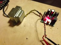
a quick question about the wall wart, will this fit? I'll install LM317 after it and set the current to 150-200mA and then U7805 as advised.
That's smp (switch mode) rubbish, better off with one of these.
GPU41090500WD00: JAMECO RELIAPRO: Power Supplies & Wall Adapters
DDU120050F0981: JAMECO VALUEPRO: Power Supplies & Wall Adapters
AD-121-ADT: OEM: Power Supplies & Wall Adapters
DDU120100: JAMECO RELIAPRO: Power Supplies & Wall Adapters
Cheers George
thanks!
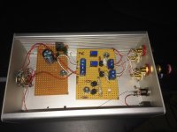
I have built mine on the previous week and thought it might be handy for all those guys who don't have time to read all the posts, so here are the main points you need to know:
schematics:
http://www.diyaudio.com/forums/analog-line-level/80194-lightspeed-attenuator-new-passive-preamp-424.html#post2713064
http://www.diyaudio.com/forums/anal...uator-new-passive-preamp-317.html#post2159480
http://www.diyaudio.com/forums/anal...uator-new-passive-preamp-182.html#post1773266
connection dots:
http://www.diyaudio.com/forums/anal...uator-new-passive-preamp-253.html#post1931676
Wax everything:
http://www.diyaudio.com/forums/anal...uator-new-passive-preamp-163.html#post1708899
http://www.diyaudio.com/forums/anal...uator-new-passive-preamp-222.html#post1832203
Adjustment with scope:
http://www.diyaudio.com/forums/anal...uator-new-passive-preamp-251.html#post1925602
PS comparison:
http://www.diyaudio.com/forums/anal...uator-new-passive-preamp-311.html#post2138093
Salas shunt:
http://www.diyaudio.com/forums/anal...uator-new-passive-preamp-247.html#post1918667
hi George,
could you pls clarify what's wrong with my lightspeed?
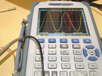
Everything works fine and attenuates as it should. When I tried to adjust one channel which is slightly louder I put 1k pot (the one on the second channel is shortened) and started the adjustment process with my scope.
There is 2v 1kHz sine wave of the output on tone generator and I got 3.29V amplitude with my scope (for instance). When I'm trying to adjust the pot, nothing happens, though the LDR changes the resistance (checked with DMM). Am I missing something or doing something wrong?
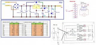
I use the following schematics.
could you pls clarify what's wrong with my lightspeed?
Everything works fine and attenuates as it should. When I tried to adjust one channel which is slightly louder I put 1k pot (the one on the second channel is shortened) and started the adjustment process with my scope.
There is 2v 1kHz sine wave of the output on tone generator and I got 3.29V amplitude with my scope (for instance). When I'm trying to adjust the pot, nothing happens, though the LDR changes the resistance (checked with DMM). Am I missing something or doing something wrong?
I use the following schematics.
Attachments
Last edited:
thanks!
the problem was solved by shorting left and right inputs when tone generator was connected. Both channels are now equal.
the problem was solved by shorting left and right inputs when tone generator was connected. Both channels are now equal.
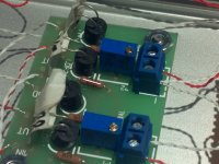
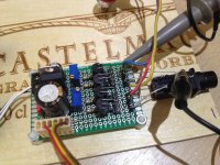
Assembled my board with 2 matched pairs of Optos and have an issue when one channel is way higher than the other. It starts from 0.8R difference when pot is in Min and 4K when pot is in Max. Max resistanse is about 14K for R and about 11K for L.
It seems that difference is growing exponentially when I turn potentiometer up. I'm able to adjust R out with trimmer only when Inputs are shorted, but still can get equilibrium. Resistance out (when In is shorted) is growing to 3.2K in mid position of potentiometer and then going down till 20R (same as starts).
I do not know how to match L and R now. Any ideas? Please
Attachments
Last edited:
Oops,
I measured potentiometer differences between L and R independently from circuit, and its behave the same as whole circuit with Optps.
I have 15k differences in max position from L to R. So, I assume this is my problem.
RadioShack potentiometer is not good for that porpoise.
Trimmer can't help since is linear and constant, and potentiometer is log.
Measure my 20K Alps Blue Velvet and it is very tight. 200R delta in Max position for 23K. Going to buy 100K Blue Velvet Alps.
No the differences in the two segments of the stereo pot don't matter.
You need to test all your ldr's again to see if they are closely matched.
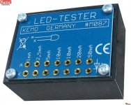
A simple cheap way is to get a $5 Kemo M078 led tester, and measure the resistances at different mA from 1mA to 20mA.
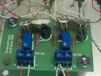
PS You only need a trimpot on the louder of the two channels, just so it can be trimmed back. Heaven forbid if you need this many trimpots, I cringe just looking at it.
Cheers George
You need to test all your ldr's again to see if they are closely matched.
A simple cheap way is to get a $5 Kemo M078 led tester, and measure the resistances at different mA from 1mA to 20mA.
PS You only need a trimpot on the louder of the two channels, just so it can be trimmed back. Heaven forbid if you need this many trimpots, I cringe just looking at it.
Cheers George
Attachments
Last edited:
If you use a kemo tester with min current of 1mA thats the same as using your 5v supply through a 5k resistor which seems to be giving you a 240ohm reading on your ldr. Hardly close the the resistance you are having problems with. If you are in fact using a switched circuit like shown in your schematics this is a great tool.
Its important to test in an area with perfect temperature. No variation. No wind/breeze. Make sure each ldr is tested the same amount of time and let them run for a good 10-15minutes before you start testing. It can get frustrating. I dont envy you. Once you get reliable matches it will be awesome.
Its important to test in an area with perfect temperature. No variation. No wind/breeze. Make sure each ldr is tested the same amount of time and let them run for a good 10-15minutes before you start testing. It can get frustrating. I dont envy you. Once you get reliable matches it will be awesome.
- Home
- Source & Line
- Analog Line Level
- Lightspeed Attenuator a new passive preamp