thanks for response
^AS I read the blog your right sir, is setting for offset, I'm noob and not my option.
what wrong with the bpa200 diagram, I put 1% tolerance of all resistors, but unfortunately the fuse is blow-out, also there's no shorted in continuity test as well in the visual test.
^AS I read the blog your right sir, is setting for offset, I'm noob and not my option.
what wrong with the bpa200 diagram, I put 1% tolerance of all resistors, but unfortunately the fuse is blow-out, also there's no shorted in continuity test as well in the visual test.
I'm sorry that i don't have a more educated response to give than "drop it in and it'll probably work".
aside from the pins for external compensation not working the same, the tl071 and ne5534 are pin compatible. and your circuit doesn't seem to use those pins.
I don't have a lot of experience with dc servos. I think once you get the amplifier to a state where it isn't blowing fuses you can figure out whether the servo is working properly with your volt meter.
Thanks for response;
Actually before I Replace the NE5534, I made a little experiment first,I test it first to the breadboard, and get the voltage after 2.21M Resistor(In the Schematic I attached) and compare to the NE5534, I got 0.001mV compare to NE5534 that have a value of 2V+ something.
Actually before I Replace the NE5534, I made a little experiment first,I test it first to the breadboard, and get the voltage after 2.21M Resistor(In the Schematic I attached) and compare to the NE5534, I got 0.001mV compare to NE5534 that have a value of 2V+ something.
The First thing I see Pin 3 on U2 goes no where and is not connected to anything.
Did you test each section individually before connecting them all together?
Also I have just read in another thread that it is not advisable to have a delayed mute operation and the the mute pin's should be wired without the capacitor for a parallel configuration as they may not have exactly the same timing per chip.
Make sure that none of the sections are oscillating.
I don't see any bypassing capacitors in your schematic, did you use any?
That is the best I can tell you right now, as I am getting ready to embark on my own First time PA and BPA chipamp projects myself.
But I can say that I know my way around opamp's very well and the very First DC servo amp I rolled up using a LT1007 and LT1210 work like a charm the first time I powered it up using a Protoboard.
Oscillations did start to become an issue once my circuit started to grow but I was able to solve that.
Having a decent scope is a must when it comes to these sorts of issues since my amplifier had a response well above 20Mhz or so as well.
The layout of these devices is very critical and I have been following all of the threads on these circuits for a very long time and in most cases (including my own) the layout can make or break having a successful operation of the circuit.
It is now time for me to get my feet wet too and see what the fuss is all about in getting these amps to work correctly.
Some never have any issues about this the very first time and for some it just seems hopeless.
This is one of the main reasons I have not made any of them yet.
But it really does inspire me when I see one that does work right off of the bat the first time as they should.
Cheers!!
jer 🙂
Last edited:
Thanks you very much sir very nice advice for the noob like me. may be I starting again,
never give-up 🙂
About the u2 pin 3 I just edited earlier the original schematic that using NE5534 replacing to TL071, and I missed that pins before I'd attached and upload,
and the bypass caps I though is it also good if I include it to the power supply section. isn't?
thanks
never give-up 🙂
About the u2 pin 3 I just edited earlier the original schematic that using NE5534 replacing to TL071, and I missed that pins before I'd attached and upload,
and the bypass caps I though is it also good if I include it to the power supply section. isn't?
thanks
Each chip needs their own set of bypass caps directly on the pins or as close as you can get them if you are doing a PCB layout.
TL071's are okay although there are opamps that have a much lower VOS as well.
Some of the TL07x's that I do have I have measured as much as 4.5mv some a little higher as well.
I have never measured a dual in my lot that wasn't way off from the other one in the same package!!
For a paralleled setup you want all of the opamp's Vos's as close to each other as you can have them.
This way there is less fighting between the stages even though your total Vos may still be 4.5mv or whatever.
A JFET input opamp is more suited than a bipolar one like the NE5534 for a DC servo due to its higher input impedance, although bipolar types can be made to work.
You always want to "drive a higher impedance with a lower impedance".
This means the 2.21Meg ohm resistor driving your servo opamp.
This is an issue, since you are driving the opamp through a 2.21Meg ohm resistor, therefore you want your DC servo opamp to have a much higher input impedance than 2.21 Meg ohms you are driving it with.
The TL07x' have an input impedance of about 10^12 ohms so this is not an issue.
The NE5534 has an input resistance of only 100K or less and this can become a big issue on your ending voltage offset of the stage as a whole.
This will make the servo try to over correct and and your overall Vos of the chipamp will be way off.
jer 🙂
for safe sir did you recommend to use 1M instead of using 2.21M?
thanks again for shedding light-on about the bypass caps,
I save this page for my reference
thanks again for shedding light-on about the bypass caps,
I save this page for my reference
A 1meg can be made to work as well just make sure you change the values around the servo as well.
The High Value resistor forms a low pass filter so that only the dc offset flow through the servo circuit.
But in the meantime it also sets the gain structure of the servo as well.
I used a 1Meg in my circuit and changed the surrounding resistor accordingly keeping the same ratios.
The gain of your circuit is set to 20 and if you used a Imeg and changed the rest (dividing by two) then the overall circuit voltage gain would 10.
This may or may not be an issue with the LM3386's as it has been said that they need at least a gain of 20 to be properly stable.
I am not up on my math for the DC servo circuit just yet but that is basically how it goes.
You see the servo has a gain of one but it has to attenuate the high frequency's.
This is done by the high value resistor.
The input voltage dc also gets attenuated so it must amplify it by the same order to feed the chipamp with the corrected offsetting input dc voltage.
Here is my circuit as the whole thing is based around a gain of 1 (unity gain).
http://www.diyaudio.com/forums/soft...re-capacitor-impedance-graph.html#post3848338
Lowering the value of the resistor will also raise the cutoff frequency of the low pas filter it forms so then you also have to raise the value of the capacitor as well in order to keep it the same.
There are many many discussions about this and the use of DC servos in these threads.
I have learned a lot from them.
In fact I am playing with DC servo circuits at this time with a regulator circuit I am working on as well only it doesn't involve any filtering at all.
From this thread,
http://www.diyaudio.com/forums/chip-amps/261125-lm3886-problem.html#post4053260
jer 🙂
Attachments

Last edited:
tl071 uses pins 1 & 5 to -ve for input bal................ the tl071 and ne5534 are pin compatible. .................
ne5534 uses pins 1 & 8 to +ve for input bal. Pin 5 is compensation.
They are not pin compatible.
tl071 upto 36V supply
ne5534 upto 44V supply
They are not supply compatible.
tl071 uses pins 1 & 5 to -ve for input bal.
ne5534 uses pins 1 & 8 to +ve for input bal. Pin 5 is compensation.
They are not pin compatible.
Right. You quoted me out of context. Pins 1, 5, and 8 are not used in the supplied schematic. So their different configuration, for the purposes of this schematic, are irrelevant.
tl071 upto 36V supply
ne5534 upto 44V supply
They are not supply compatible.
I believe this is also moot in this particular circuit
Thanks for response;
Actually before I Replace the NE5534, I made a little experiment first,I test it first to the breadboard, and get the voltage after 2.21M Resistor(In the Schematic I attached) and compare to the NE5534, I got 0.001mV compare to NE5534 that have a value of 2V+ something.
Yes - input currents are not just an abstract concept. The TL071 has a FET input, with much higher impedance than the BJT input on the NE5534.
thanks
noted sir
Can I get advantages If I use dual chip opamp for DC servo like TL074 compare to TL072 which single chip?, I
was thinking if I use dual chip opamp to be more identical output offset voltages, and to get very close output for paralleled the two lm3886.
So I test first the 4 LM3886 so that I'm sure that there's no damage.
Attachments
Last edited:
HI again
I want to use trimmer to be sure that the DC offset of the servo in parallel is equal, and without fighting each other.
Is my attach image is the right ways to test and trimmed the DC servo?
Helps thanks
I want to use trimmer to be sure that the DC offset of the servo in parallel is equal, and without fighting each other.
Is my attach image is the right ways to test and trimmed the DC servo?
Helps thanks
Attachments

Last edited:
I already answered this in post #6!
"I have never measured a dual in my lot that wasn't way off from the other one in the same package!!"
Measure your devices to see if they match or not.
I was planning on using one of the LME49xxx series opamp's (860 or 720, I don't remember at this time) as a servo as it had a Vos of about 1.5mv or less but the other half was at 8.5mv!
And even though this was within TI's spec it was not suitable for use in my PA design.
All of the samples I have of that particular part had the exact same measurements. 🙁
Of the TL07x's I have, they don't match up when it comes to the Dual's and Quad's either .
A couple of them were close sorta and all of the rest that I have are way off!!
I couldn't even find a matching pair.
Typically the TL07x's I have, Have about 4.5mv and rarely down to about 2.5mv of Vos.
The other half was typically much more in to the 6mv to 8mv range or so.
This is one of the main reasons I have not built a PA design yet for searching of suitable opamps for the servos.
Back when I first started at studying this type of design, precision opamp's such as the LF411's and LF412's were quite expensive and in some cases as much as if not more than the cost of the chipamps themselves.
Thankfully this is not the case anymore.
I was not in the mood at the time to be blowing up some Chipamp IC's as many have done without knowing why it happens.
So I read a lot, and a lot, and for many years on the subject.
I have had my LM4780's since 1994 and I have still not used them yet because of stories of drastic failures.
And still read about them.
Every part is different so they must be measured to be sure.
Consider if you use a .1ohm resistor on the output of each chip amp and their is a 5mv difference in VOS between two of them then as much as 25ma of current will be flowing between the outputs through the two .1 resistors of the two devices due to the offset.
Compound this if you add more stages and one of the chipamps will be handling the bulk of this and currents can be as high a 100ma or so depending on the offset differences if not more!
This is just common opamp knowledge here.
You don't save any board space using Dual or Quad opamps much either the layout just gets to cluttered.
I have started on such a design and it is not very easy to do and make it compact!!
Although not impossible to do.
The layout gets very critical in order to maintain a certain level of performance as shown in recent threads.
Do read through those threads and study everything that is presented in them and then apply that to a single stage as suggested by AndrewT.
Just because you are using a DCservo does not mean that the thing will not sit there and oscillate, heat up and destroy itself.
This gets even worse when you start to parallel and bridge them.
In order for multiple stages to be stable you must First learn how to make a single stage stable.
I have learned this on my own as well with many different types of designs, only I have not pursued the common Chipamp's as of yet except for the LT1210's.
The biggest issue that you are/will have is using an opamp that doesn't have a Vos of at least guarantied less than 1mv.
I have researched this quite extensively and there are quite a few nice Dual's and Quad's that are better suited for such a beast, not to mention single opamp's as well.
I don't know exactly what is available to you.
jer 🙂
Look at page 8 and 16 of this datasheet to reference the proper termination of the offset pins of the TL071.
http://www.ti.com.cn/cn/lit/ds/symlink/tl072.pdf
jer 🙂
http://www.ti.com.cn/cn/lit/ds/symlink/tl072.pdf
jer 🙂
thanks you sir for clearing my mind;
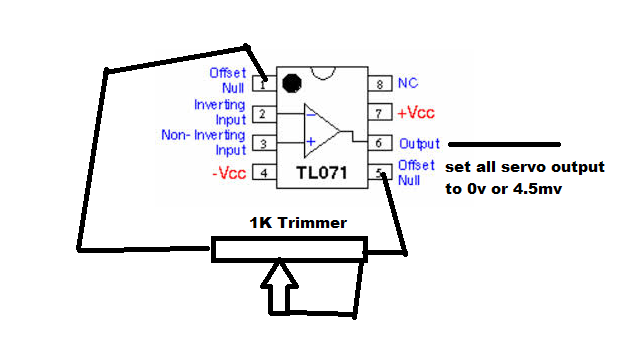
Is this the right ways to test the DC servo and trimmed the TL071?
Is this the right ways to test the DC servo and trimmed the TL071?
No!!
Refer to the data sheet in the previous post.
or here,
https://www.google.com/search?q=tl0...ZKYeKyATeyYKwDw&ved=0CH4QsAQ&biw=1280&bih=865
jer 🙂
Refer to the data sheet in the previous post.
or here,
https://www.google.com/search?q=tl0...ZKYeKyATeyYKwDw&ved=0CH4QsAQ&biw=1280&bih=865
jer 🙂
Last edited:
thanks again
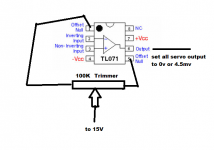
so sir my only concern is to set to 1mV(pin6 output) all servo-output in paralleled?
(pin2 - in)(pin3 +in) is no need to test?

VCC +15 if not inverted? if inverted to VCC -15v?
so sir my only concern is to set to 1mV(pin6 output) all servo-output in paralleled?
(pin2 - in)(pin3 +in) is no need to test?
VCC +15 if not inverted? if inverted to VCC -15v?
Attachments
Last edited:
- Status
- Not open for further replies.
- Home
- Amplifiers
- Chip Amps
- BPA-200 servo problem