Hi!
I play bass through a tube preamp into a class D PA power amp. My old one, a Peavey IPR1600 was great for this - until it suddenly stopped working. The Peavey is far too complicated for me to try and fix, so I decided to ditch it (maybe have it fixed later) and this time build a new one from Hypex modules (namely Ucd2kOEM and PSU SMPS3k).
Now there's two "problems" when using a Hypex PA module for instrument use (I've done this once before with a Ucd180ST). 1, they want a balanced signal, and 2, the line level output voltage from an instrument preamp may vary greatly.
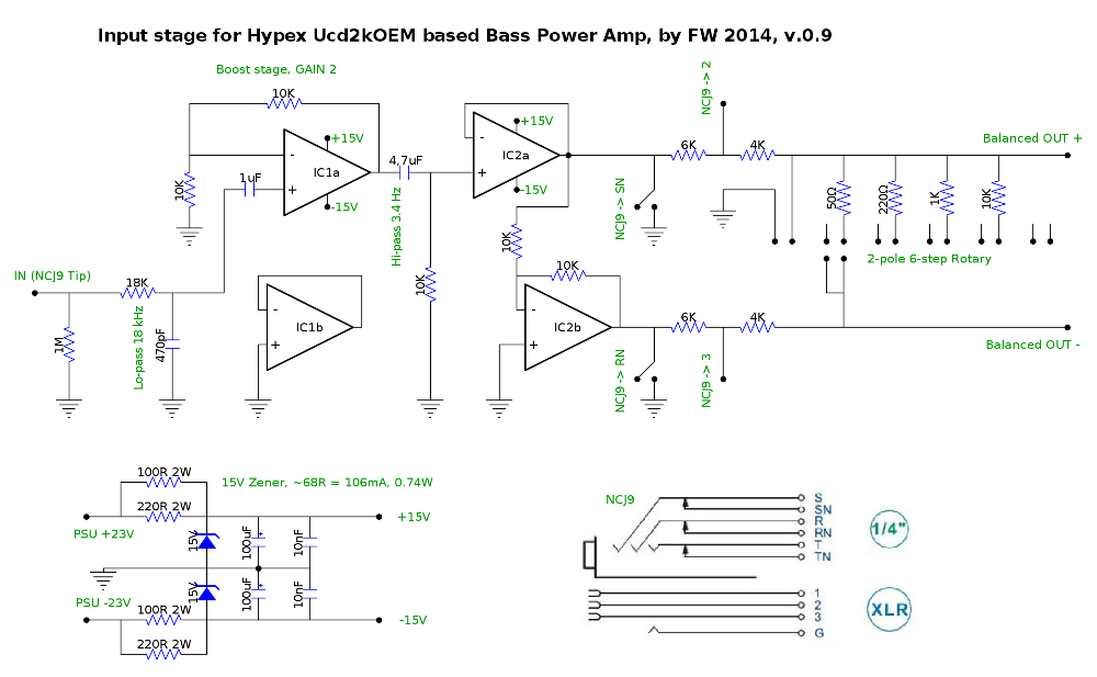
So I decided to include a small opamp stage that amplifies the signal and has a balanced output. (If the preamp already has a balaced signal, it will bypass this stage.) I also wanted some kind of attenuator to be able to drive the preamp hard without clipping the Ucd (or blowing the speaker).
A few notes:
- The idea of the switched XLR-1/4" combo jack is, that the opamp line driver output is grounded when XLR is used.
- Non usable frequencies are R/C-filtered, don't know if this is really needed.
- A more sophisticated regulator would probably be better, but this is simple and I have zeners handy.
- Opamps will be OPA2134 or NE5532.
- The values for the stepped attenuator are just thown in for now, I'll adjust them when the thing is built and I can try what works best.
- DC blocking caps on the output are left out intentionally, the UcD should take care of this.
It is still under development and may contain lots of errors. Comments are appreciated. Here goes:
I play bass through a tube preamp into a class D PA power amp. My old one, a Peavey IPR1600 was great for this - until it suddenly stopped working. The Peavey is far too complicated for me to try and fix, so I decided to ditch it (maybe have it fixed later) and this time build a new one from Hypex modules (namely Ucd2kOEM and PSU SMPS3k).
Now there's two "problems" when using a Hypex PA module for instrument use (I've done this once before with a Ucd180ST). 1, they want a balanced signal, and 2, the line level output voltage from an instrument preamp may vary greatly.
So I decided to include a small opamp stage that amplifies the signal and has a balanced output. (If the preamp already has a balaced signal, it will bypass this stage.) I also wanted some kind of attenuator to be able to drive the preamp hard without clipping the Ucd (or blowing the speaker).
A few notes:
- The idea of the switched XLR-1/4" combo jack is, that the opamp line driver output is grounded when XLR is used.
- Non usable frequencies are R/C-filtered, don't know if this is really needed.
- A more sophisticated regulator would probably be better, but this is simple and I have zeners handy.
- Opamps will be OPA2134 or NE5532.
- The values for the stepped attenuator are just thown in for now, I'll adjust them when the thing is built and I can try what works best.
- DC blocking caps on the output are left out intentionally, the UcD should take care of this.
It is still under development and may contain lots of errors. Comments are appreciated. Here goes:
Input amp has no DC-bias on non-inverting input: The 1uf coupling cap must be moved towards input jack.
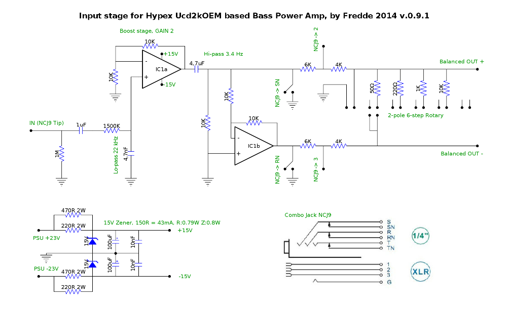
There is no need for a voltage buffer between input amp and non inverterted output - you can skip this buffer.
Having said this you will need only one dual opamp.
There is no need for a voltage buffer between input amp and non inverterted output - you can skip this buffer.
Having said this you will need only one dual opamp.
You're right, it's for blocking possible DC from a previous source. I'll move it.Input amp has no DC-bias on non-inverting input: The 1uf coupling cap must be moved towards input jack.
It's not only a buffer, but a gain stage (now set to a gain of 2), this is because (see above) i want to be able to boost the input signal in case it's too low. The UcD needs 2.25V input according to the datasheet if you want to drive it to the max.There is no need for a voltage buffer between input amp and non inverterted output - you can skip this buffer.
Having said this you will need only one dual opamp.
But maybe I could remove this stage and put gain resistors on the balanced driver instead? The same result with less parts is all good to me.
Sorry, thought you meant IC1, now see what you mean. And you're right, I could take out IC2a and leave IC2b as it is unity gain and takes its input from IC2a. The balanced signal should stay correctly balanced, right?
Ok, did a few modifications, moved the input cap and pulled out the other opamp as suggested.
I also (now that we only have one opamp) scaled down the zener-circuit a bit, it's now at max 43 mA. Should be enough for one opamp I think.
I also (now that we only have one opamp) scaled down the zener-circuit a bit, it's now at max 43 mA. Should be enough for one opamp I think.
That is better now, but
n.inverting input of input OPA is not biased yet - in fact it is floating. You should move the 1meg resistor to the other side of the decoupling cap thus providing a DC path for non inv input.
The zener circuitry is a bit ugly with a power dissipation of 15V*43mA > 0,6W.
You would better use linear regulators 7815/7915 instead.
It is no good practice to mute the circuitry by directly shorting OPA-outputs.
Last edited:
The input low pass 22kHz is correct assuming zero ohm impedance of the input signal source. This will be fine with an instrument fitted with active electronic on board, often found in modern bass guitars.
Using the classic bass guitar with passive circuitry, impedance may be several 100kOhms - in combination with 4n7 lowpass cap resulting in a real treble killer circuit.
I found a typo at lopass resistor - its value must be 1500 ohms
Using the classic bass guitar with passive circuitry, impedance may be several 100kOhms - in combination with 4n7 lowpass cap resulting in a real treble killer circuit.
I found a typo at lopass resistor - its value must be 1500 ohms
Last edited:
1) as noted, you need to provide a continuous DC path from IC1a input to ground.
The 1uF cap is fine (although a 0.1uF one is better, much closer to real needs).
2) the stepped attenuator idea is fine, but I guess the possible range of signals present at the input will be easily handled by a simple volume pot, straight at the input.
100K to 1M should be easily driven by your tube preamp.
Easier to find linear taper is acceptable, because it´s not a full range volume control but simply a "sensitivity adjuster" with less necessary range.
You just set it to a convenient point and leave it there.
And grounding the input of IC1A is a fine mute control.
Ok, I somehow thought this wasn't necessary on a dual supply design, but sure, I'll include one. What would be a suitable value?1) as noted, you need to provide a continuous DC path from IC1a input to ground.
The 1uF cap is fine (although a 0.1uF one is better, much closer to real needs).
2) the stepped attenuator idea is fine, but I guess the possible range of signals present at the input will be easily handled by a simple volume pot, straight at the input.
100K to 1M should be easily driven by your tube preamp.
Easier to find linear taper is acceptable, because it´s not a full range volume control but simply a "sensitivity adjuster" with less necessary range.
You just set it to a convenient point and leave it there.
And grounding the input of IC1A is a fine mute control.
This is exactly what I thought myself at first, but then the pot would be bypassed when using the XLR input. I still want the volume control to be functional when using a balanced input signal. I could, of course, have a separate balanced line receiver op-amp stage first, but that feels a bit convoluted. (I rearely use an XLR feed, but I this is pretty standard on power amps, so I wanted to include this possibility for future needs.)
The stepped attenuator is more suitable for my needs than a regular pot - I want a set-and-forget control that won't move accidentally. I do all on-stage adjustments on the preamp master vol, and this power amp will probably have enough power to blow my speaker, which is less likely with a stiff rotary switch. (I could still use a 10K (trimmer wired) pot in the same place as the attenuator is now, it's just a matter of preference.)
The input low pass 22kHz is correct assuming zero ohm impedance of the input signal source. This will be fine with an instrument fitted with active electronic on board, often found in modern bass guitars.
Using the classic bass guitar with passive circuitry, impedance may be several 100kOhms - in combination with 4n7 lowpass cap resulting in a real treble killer circuit.
I found a typo at lopass resistor - its value must be 1500 ohms
Yes it's a typo, it should read 1k5, thanks!
This is a power amp not intended to be used directly with a passive pickup, my preamp can drive a 16 ohm load. But you're probably right. Maybe I should just skip the filter(s) altogether, I don't even know if they serve a real purpose.
Yes, I know. I just happen to have 15v zeners in my drawer, and it felt like a comfortable choise as I've used them sucessfully before. But I'll look into a regulator based supply. The most important thing is that this amp is reliable, I don't want it to fail during a gig.]The zener circuitry is a bit ugly with a power dissipation of 15V*43mA > 0,6W.
You would better use linear regulators 7815/7915 instead.
It is no good practice to mute the circuitry by directly shorting OPA-outputs.
Ok, I see. Because he op-amp has a short-circuit load? I'll just mute the input at the switch jack instead.
Last edited:
You will find that a small zener dissipating 0,6W will heat up >100C easily. This is what we call a hotspot, and from a viewpoint of reliability should be avoided.
Thanks, you've got me convinced. I'll do this instead (circuit straight from the UA7800 datasheet):

I don't know if the (here greyed out) "Reverse-Bias Protection" diodes are really needed, but i've got lots of diodes and I'll include them if they don't have any negative effects.
Edit: Will I need to heatsink the regulators?
I don't know if the (here greyed out) "Reverse-Bias Protection" diodes are really needed, but i've got lots of diodes and I'll include them if they don't have any negative effects.
Edit: Will I need to heatsink the regulators?
If your current consumption is 10mA or less, and your voltage drop along the regulator is less then 10V - internal power dissipated inside each regulator will be less than 200mW - so you will not need any heatsink for the regulators.
I am not sure whether the catch diodes are really necessary, in any case the won't do any harm.
I am not sure whether the catch diodes are really necessary, in any case the won't do any harm.
Ok thanks. I think I'll put small snap-on heatsinks there anyway in case I want to use this supply for some additional circuit in the future. Lots of space in the enclosure, and these heatsinks cost next to nothing.
Hypex UcD2k / SMPS3k power amp build finished
Hi,
I noticed that I never reported back on how this project turned out, and we all know how annoying it is to find an interesting build thread and then never get to know how and if the project was successful...
Well, this build turned out pretty good. I've done around 20 gigs with it so far with no problems. It has all the power I'll expect to need now and in the future, and it has the features I need for my stage setup.
Final schematic of the input stage:
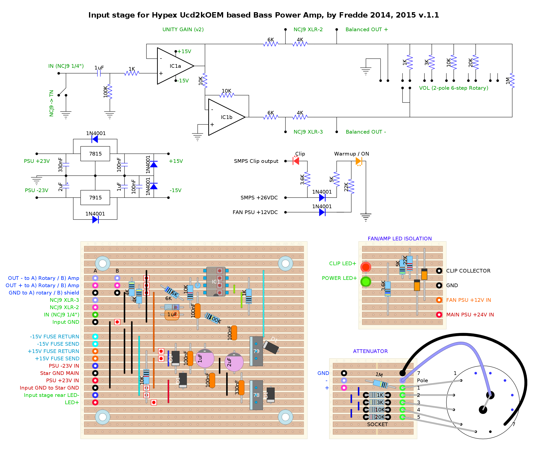
The "warmup led" is the power led glowing dimly until the main PSU powers up. This is is powered by the fan supply, so it's also an indicator the fan supply still works. The attenuator resistors reside in a DIP-8 socket, which allows you to fine tune the attenuator stepping without soldering.
I actually don't know if the fan is really needed, and the UcD will go into protective shutdown if it overheats, but I wouldn't want that to happen in the middle of a gig so I included a fan just in case. The heatsink is also not overly big.
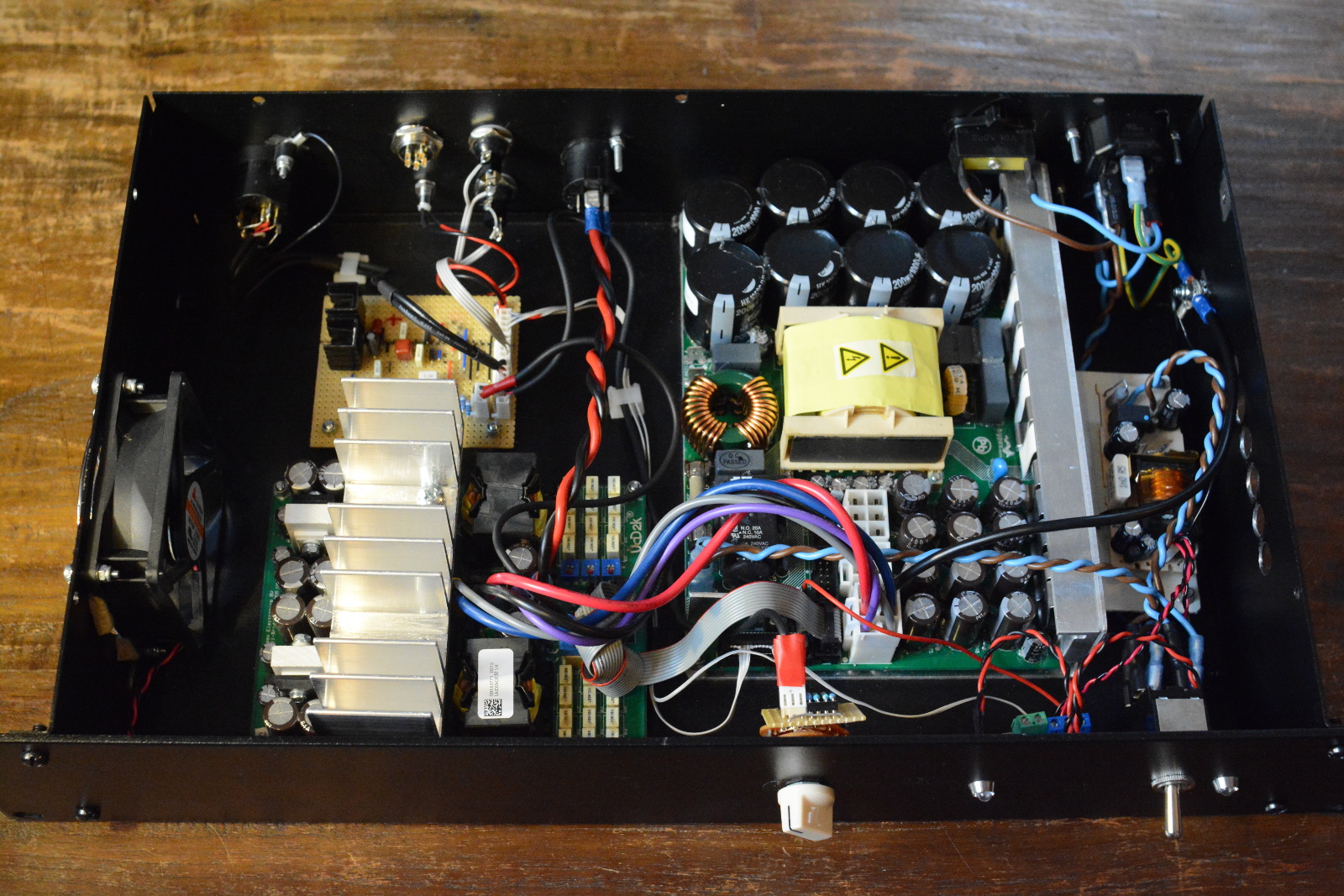
Guts:
Back:
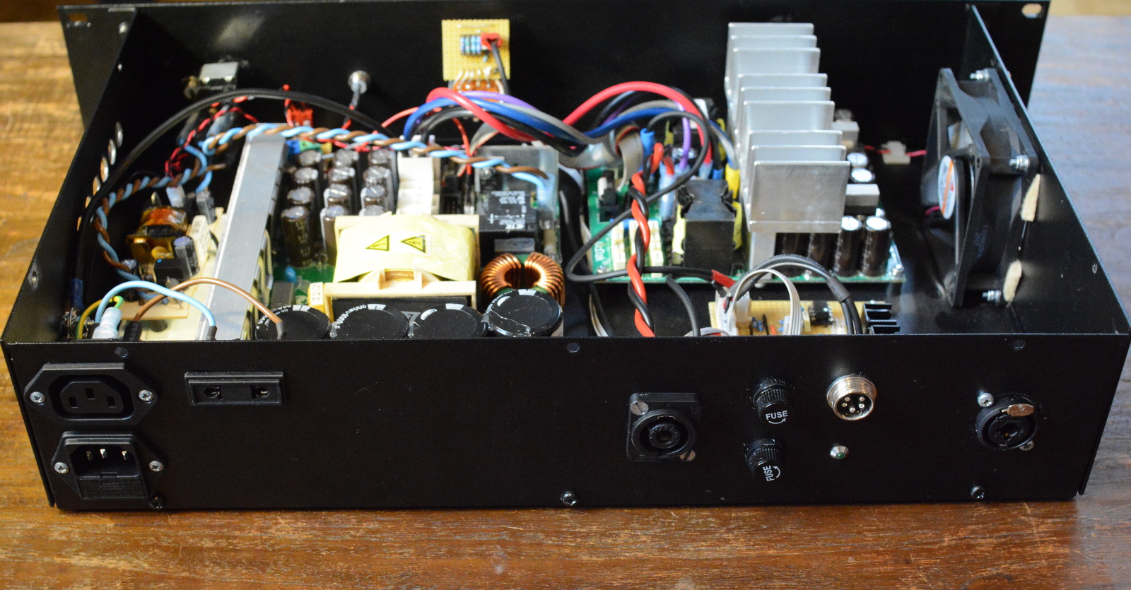
The GX16 5-pin connector was supposed to be a ±15V output for external op amp stuff, but I ended up not needing it, so right now it's just plugging a hole. The fuses and led guard the input stage supply rails. The extra EU outlet powers my pedal board (the IEC is for the preamp, of course), this way I only need one power outlet on stage.
Front:
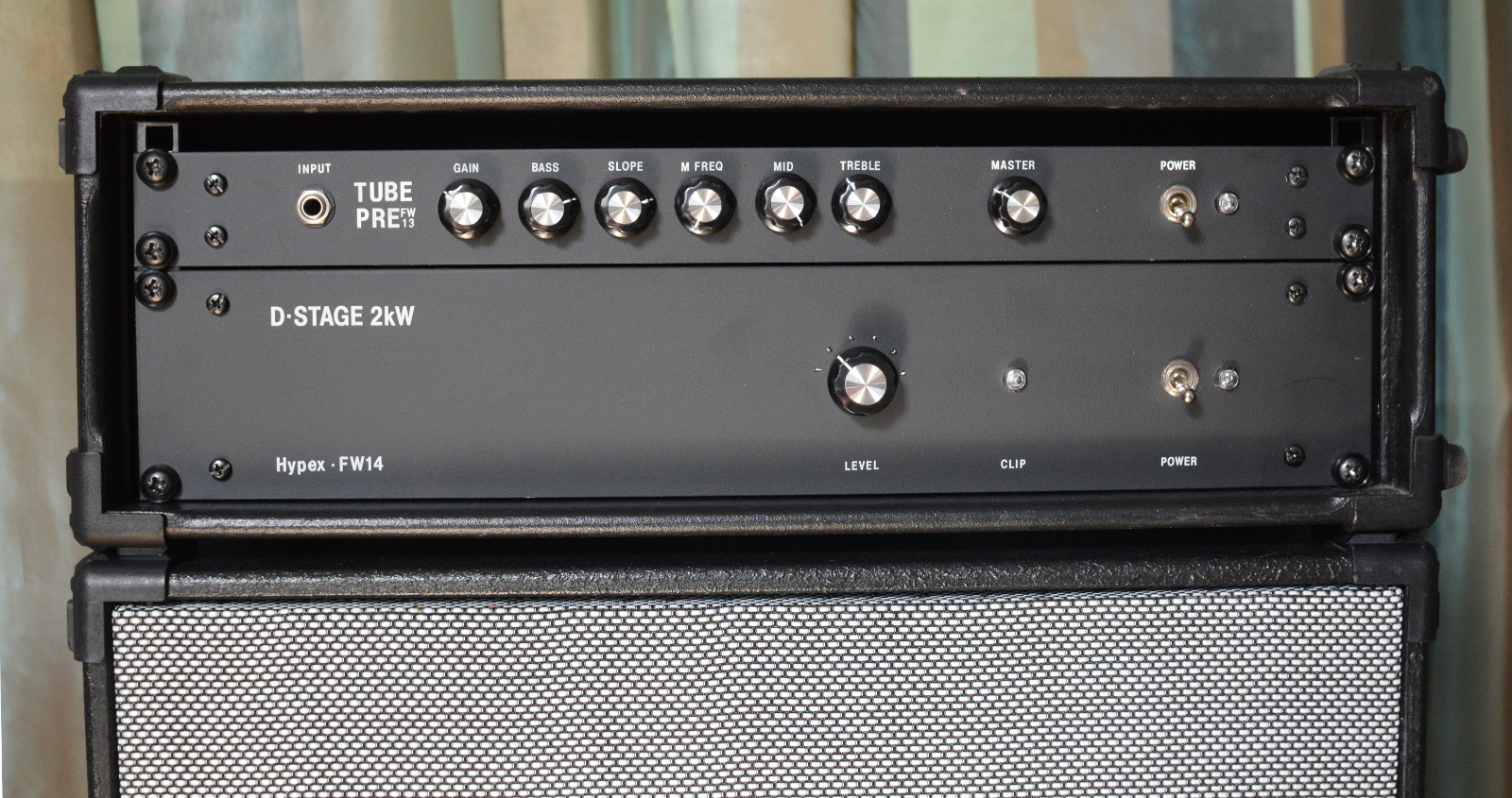
The preamp and cab are also my builds, the cab is a fEARful 15/6.
/Fredde
Hi,
I noticed that I never reported back on how this project turned out, and we all know how annoying it is to find an interesting build thread and then never get to know how and if the project was successful...
Well, this build turned out pretty good. I've done around 20 gigs with it so far with no problems. It has all the power I'll expect to need now and in the future, and it has the features I need for my stage setup.
Final schematic of the input stage:
The "warmup led" is the power led glowing dimly until the main PSU powers up. This is is powered by the fan supply, so it's also an indicator the fan supply still works. The attenuator resistors reside in a DIP-8 socket, which allows you to fine tune the attenuator stepping without soldering.
I actually don't know if the fan is really needed, and the UcD will go into protective shutdown if it overheats, but I wouldn't want that to happen in the middle of a gig so I included a fan just in case. The heatsink is also not overly big.
Guts:
Back:
The GX16 5-pin connector was supposed to be a ±15V output for external op amp stuff, but I ended up not needing it, so right now it's just plugging a hole. The fuses and led guard the input stage supply rails. The extra EU outlet powers my pedal board (the IEC is for the preamp, of course), this way I only need one power outlet on stage.
Front:
The preamp and cab are also my builds, the cab is a fEARful 15/6.
/Fredde
Cool 🙂
Very nice build 🙂
Just to have the full project in one page, please post the tube preamp you use to drive it .
Very nice build 🙂
Just to have the full project in one page, please post the tube preamp you use to drive it .
Thanks!
The preamp is described here: http://www.diyaudio.com/forums/inst...port-tube-preamp-bass-guitar.html#post4409749
I think a vintage style tube preamp and a power amp built from modern class D modules are so fundamentally different that I thought it best to keep them separated. They are separate projects that just happen to live in the same rack 🙂
Having said that, I think a tube preamp with a class D power amp is a perfect combination (or compromise) for a bass amp. You get a nice tube sound from the preamp and a great watts-to-weight ratio from the power amp.
- Status
- Not open for further replies.
- Home
- Live Sound
- Instruments and Amps
- Hypex UcD2kOEM Bass Power Amp Project