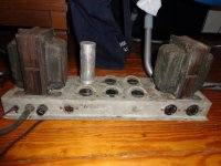
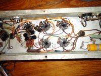
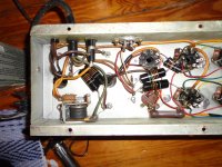
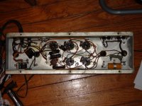
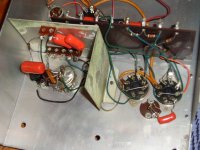
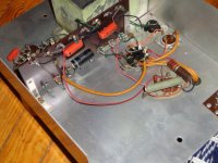
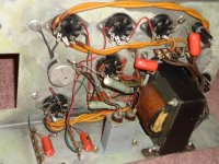
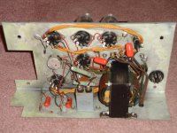
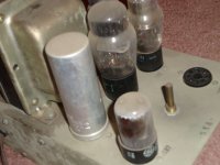
I found Baldwin organ amp I'd like to convert to home audio use, mostly as a way to learn more about tube amps. This one didn't come from a console, but I think it was used as a dedicated amp for an external speaker - like a Leslie speaker but with no rotating horn. It was mounted on the wall in the back room of an old masonic temple, so I thought it was a PA amp at first, until I saw the Baldwin tubes. Pics are below - after I cleaned all the bird turds off!
It looks different than most of the other Baldwin amps on the forum in that it has no 12AX7 or other small signal tubes in it. I'm not interested in making it stereo, if that's even possible - I don't know much about tube amps but it seems this one is mono all the way. I don't want to put out the money for output transformers for this one anyway - so I'll either find a mate and use them as monoblocks or power my center speaker with it in my 5.1 setup.
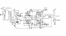
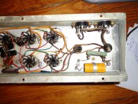
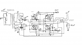
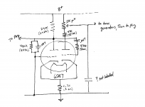
So - what do I need to do with this to make it work in my home system, besides recapping and replacing some deteriorated wire? I've sketched out the schematic as well - as you can no doubt see I have no idea how things are arranged inside the transformers, so I probably have that part wrong. Any help/corrections would be appreciated.
 very large inline images replaced with resized attachments
Please see here: http://www.diyaudio.com/forums/everything-else/183084-pictures-why-not-attach-them.html
It looks different than most of the other Baldwin amps on the forum in that it has no 12AX7 or other small signal tubes in it. I'm not interested in making it stereo, if that's even possible - I don't know much about tube amps but it seems this one is mono all the way. I don't want to put out the money for output transformers for this one anyway - so I'll either find a mate and use them as monoblocks or power my center speaker with it in my 5.1 setup.
So - what do I need to do with this to make it work in my home system, besides recapping and replacing some deteriorated wire? I've sketched out the schematic as well - as you can no doubt see I have no idea how things are arranged inside the transformers, so I probably have that part wrong. Any help/corrections would be appreciated.
very large inline images replaced with resized attachments Please see here: http://www.diyaudio.com/forums/everything-else/183084-pictures-why-not-attach-them.html
Attachments
Last edited by a moderator:
I think you have the B+ PSU filter wrong. CLC topology is what I'd expect to find. I also think you have signal the topology wrong. The primary of the O/P transformer will be center tapped and a pair of 6L6s will be connected to each end of the primary.
You show only power O/P tubes and a rectifier. You will have to build driver and phase splitter circuitry.
While they may have been good in their day, those old "bumblebee" coupling caps. have got to go. Replace them with a mix of Soviet surplus K40 paper in oil (PIO) and 716P series "orange drop" parts.
Check the carbon composition resistors for drift and noise. Except in grid stopper positions, replace the carbon comp. parts with carbon film parts of appropriate wattage rating.
Might the original driver and phase splitter circuitry have been in the console? (I think I can get access to it) I'll have to learn what you mean by those terms....can you point me to a reference?
I thought I had the transformer connections wrong. What puzzled me was the connection of the 6L6 pins #8 to the OP secondary. Why is that connection there?
So I suppose this amp can't be used as-is (after part replacement) - that's what I'm gathering here.
I thought I had the transformer connections wrong. What puzzled me was the connection of the 6L6 pins #8 to the OP secondary. Why is that connection there?
So I suppose this amp can't be used as-is (after part replacement) - that's what I'm gathering here.
I think the B+ filter is just LC - there aren't enough capacitors in there for CLC. I made a few corrections to the schematic - the power filter cap is connected to pin 4, not 3, of the nearest 6L6, and the + end of the power cap is connected to the OP primary, presumably to the center tap you mentioned.
Attachments
Yes it probably is. But it may be integrated with the organ tone generating circuits (chassis) and inconvenient to separate. You can get some information about phase inverters/splitters from the Valve WizardMight the original driver and phase splitter circuitry have been in the console?
The cathodes are coupled through the output transformer with a separate winding. By doing so this provides some local feedback to help reduce distortion.What puzzled me was the connection of the 6L6 pins #8 to the OP secondary. Why is that connection there?
This is correct. And before I did anything else I would verify the transformers are good. DC resistance checks and preferably hipot testing the OPT with around 500 volts DC, or half that if AC. They look pretty old and weathered.So I suppose this amp can't be used as-is (after part replacement) - that's what I'm gathering here.
Last edited:
I don't have the equipment for a hipot test - when you mention a DC resistance test, are we looking for infinite resistance between the primary & secondary?
Yes, and also from windings to the core. But continuity within each winding....when you mention a DC resistance test, are we looking for infinite resistance between the primary & secondary?
The OP secondary, power primary & B+ secondary are OK, but the OP primary & heater secondary show resistances in the 60 ohm range. There are also measurable resistances between the windings & core in both transformers - it jumped around a bit, averaging on the order of 5Mohm but dipping as low as 100K. I guess this iron is shot, unless I can open it up and clean things out a bit. Well - on to the console, which I should be able to access later this week, and which hopefully has not doubled as a bird roost these last 40 years or so.
Well, this doesn't sound good. Any measurable resistances between windings and/or the core is not good. It may be leakage from humidity or moisture that has gotten into the transformers. Make sure that all wires are disconnected when measuring this. Also be very certain not to touch any bare ended wires with your fingers when making these measurements because your skin resistance will affect high megohm readings. And even a very light touch will do this. On a good transformer the most you may see is a slight up-kick on the highest range from the internal distributed capacitance charging up. But this will quickly return to virtual infinity.
I guess the most you could try is to bake them at low a temperature (100º) and possibly drive it out. But if the wires are hard and dry I wouldn't even bother with it as they're probably too far gone. Also, if you remove the end bells, be careful to notice any insulating shoulder washers on the bolts and not loose them. They are there to prevent shorting out the laminations magnetically.
You also have to ask yourself why was this amp hanging on the wall and not in the console where it belonged?
I think it was for the add-on external speaker only. If I find an amp in the console (and I bet I will) I'll probably just ditch this one and not even try to rescue the transformers.
Zinser makes a "Amber Shellac" I get from Home Depot. I have a hoard of old "Octal" used transformers that react well every time to this dipping process. Like was already mentioned, a bakeout is recommended, then go directly into the shellac dip. The only other thing I would recommend is to somehow pull a vacuum & vent a few times to inject the liquid into the tight spots, as I have the luxury of such apparatus, however simple dipping with the end covers removed might save these beauties. Good luck, Doug
The console did indeed have an amp - though it's not Baldwin, but Minshall. I thought it would be Baldwin since the external speaker amp had Baldwin tubes in it. Anyway, here it is, and it appears to be a complete mono amp. I'll try to get the schematic this week. It also had a bank of tone generators - very modular, from which I scored a load of 12AX7 tubes. Also there's an effects unit of some sort, which I took.
Attachments
-
 DSC01535alt.jpg703.2 KB · Views: 79
 -
 DSC01534alt.jpg653.8 KB · Views: 63
 -
 DSC01533alt.jpg680.1 KB · Views: 69
 -
 DSC01532alt.jpg718.7 KB · Views: 157
 -
 DSC01531alt.jpg653.7 KB · Views: 168
 -
 DSC01530alt.jpg736.5 KB · Views: 149
 -
 DSC01529alt.jpg668.9 KB · Views: 149
 -
 DSC01528alt.jpg721.1 KB · Views: 180
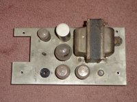
I tried to trace out the schematic (I'm still at it) but I'm pretty sure this isn't a complete amp but rather a power supply. Both transformers are power units and what I thought were output tubes were actually VR150 voltage regulators. There is a 6SN7 GTA tube which I suspect may be part of the phase splitter - maybe I can make a whole amp out of the two parts, providing I can resurrect the transformers on the other unit. I don't remember if there was a speaker in the console. I might have to go back and look. If nothing else I'll learn a bit from this.
I'm hoping someone can help me out here - I'm not sure what I'm looking at. I traced out the schematic around the 6SN7 tube, and at first I was sure it was a long-tailed pair phase splitter but now I'm not sure. There doesn't seem to be enough in/out connections and they're in the wrong places. Does anyone recognize this? I may just have to rewire the whole thing (a daunting task at this point considering what I don't know yet!) The nominal resistor values are given, along with the measured values in parentheses.
Attachments
For a minute i thought you had one of those BIG Baldwin 40watt monoblocks that they used in the Baldwin Tone Cabinets for organs. I had one of those once... dual rectified 5U4G, 6SN7's and a quad of 6L6's. ( and the biggest damn PT i can remember seeing in a tube amp )
On closer inspection of your initial picture, that is not the case ( as you have confirmed ). Your setup looks much smaller.
The thing i find works best when you have unknown electronics is to start googling codes stamped on things. Both the PT and OT should have a code stamped into them that will tell you the manufacturer and date. Use those, and the tube compliment to google and determine what it came out of. Radiomuseum usually ends up being my final destination. It is rare when i don't end up with a schematic of what i was looking for within 15 minutes.
The "HOA" Hammond Organ Amp Part Number
yup... hammond organ parts all start with "AO-" something. Another easy way to find out what something is out of, if it was ever in a hammond.
Thanks for the input, guys. I've had no luck with Google so far - no codes anywhere except on the PT, and that was a supplier code. Actually with a bit of work I can finish tracing out the schematic, for it's not that complicated. I really would like to know what the 6SN7 is doing though.......after I learn a bit more I might just configure a long-tailed pair splitter around it and run it into the 6L6 stage and see what happens.
- Status
- Not open for further replies.
- Home
- Amplifiers
- Tubes / Valves
- Baldwin organ amp