Does anyone happen to have H-parameter charts or a datasheet with them for any of the BC5xx transistors? Or any other useful transistors for that matter?
The reason I ask about the H-params is that based on my amplifier prototype the RF transconductance of the BC550C (Fairchild) is 2-3x worse than Cordell's SPICE models.
Here it is:Does anyone happen to have H-parameter charts or a datasheet with them for any of the BC5xx transistors? Or any other useful transistors for that matter?
Attachments
Does anyone happen to have H-parameter charts or a datasheet with them for any of the BC5xx transistors? Or any other useful transistors for that matter?
I have some, give an address I can send it all to.
Here it is:
Thanks, unfortunately it's not what I wanted. There are some datasheets that give the H-param vs Frequency charts. These allow you to very accurately model the RF behavior. For instance:
https://www.engineering.uiowa.edu/sites/default/files/ees/files/NI/pdfs/01/31/DS013193.pdf
Here are some models for the MPSH10/MPSH81 (unfortunately obsoleted) that I quickly modified some time ago to improve the accuracy of shunt regulator simulations I was doing. I didn't change anything except the RF parameters:
.model MPSH81 pnp IS=1.364229E-15 BF=109 NF=1 ISE=1.59087E-16 NE=2 VAF=100
+ ISC=5.8e-9 BR=0.48 IKR=0.85 IKF=0.150527 RB=46.6 RBM=0.159 IRB=1.51356E-6
+ RE=0.23 RC=1.0 CJE=2.63E-12 VJE=0.80 MJE=0.335 FC=0.5 CJC=2.77E-12 VJC=0.757
+ MJC=0.158 XTB=1.59999 EG=0.86 XTI=3 TF=97.83e-12 ITF=69.29 VTF=10
+ XTF=599e-6
.MODEL MPSH10 NPN(IS=5.6E-16 ISE=6.367E-15 ISC=1E-15 XTI=3
+ BF=133 BR=8 IKF=2.5E-2 IKR=1E-2 XTB=1.5
+ VAF=40 VAR=6 VJE=1.195 VJC=0.5617
+ RE=0.65 RC=1.8 RB=150 RBM=0.5 IRB=5E-4
+ CJE=1.012E-12 CJC=1.197E-12 XCJC=0.75 FC=0.5
+ NF=1 NR=0.99 NE=1.75 NC=1.167 MJE=0.4496 MJC=0.2588
+ TF=6E-11 TR=40.5E-9 ITF=0.27 VTF=10 XTF=30
+ EG=1.11 KF=1E-9 AF=1
+ VCEO=25 ICRATING=50m MFG=ZETEX)
.model MPSH81_k AKO:MPSH81 Fc=0.9 Itf=1.15 Vje=.75 Vtf=10 Xtf=10 Tf=87p
.model MPSH10_k AKO:MPSH10 (Fc=0.9 Itf=2 Vje=.75 Vtf=10 Xtf=10 Tf=90p Rb=47)
The first two are the standard models and the last two with the _k suffix are my improvements. Separating them will break them because the latter references the former.
Transconductance vs Frequency is a characteristic that isn't strongly related to Ft, but is very important in the MHz region and can have an effect on feedback loops. Ft vs Ic charts aren't sufficient to model this.
Last edited:
I am afraid this data is generally not available for LF transistors. The MPSH series are RF transistors
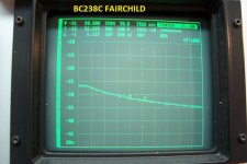
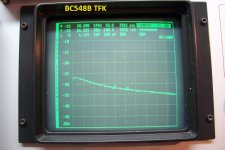
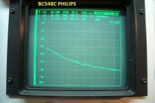
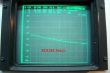
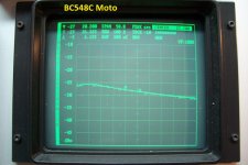
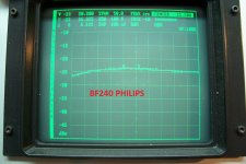
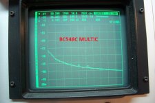
I made some measurements on a number of samples from various manufacturers.The reason I ask about the H-params is that based on my amplifier prototype the RF transconductance of the BC550C (Fairchild) is 2-3x worse than Cordell's SPICE models.
These are not "metrological" grade measurements: they are scalar, uncalibrated, and made on something that is more a toy that anything, but it gives a taste of what it looks like, and there are significant differences between founders.
I may repeat those measurement on a properly calibrated VNA, but it will take some time.
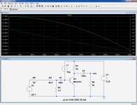
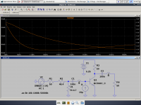
The first pic shows the equivalent circuit of the test jig; for not too high frequencies, it should return the value of gm without too many parasitic effects.
Vce is 5V and Ic 5mA (the bias is adjusted for Ic).
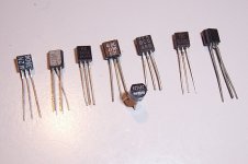
Second pic is the parade of DUT's
From left to right: 2N3904 Moto, BF240 Phil (gold standard), BC548C Moto, BC413B Sesco (=Silec, Thomson, ST, ), BC548C Philips, BC548B Telefunken, BC548C Multicomp, BC238C Fairchild.
There are indeed significant differences, between devices and also between the reality and simulation.
PS:
the measurement range is ~0 to 50MHz
Moderators: if you could split the posts pertaining to this particular subject from this thread and create a new discussion in solid state, it would be a good thing
Attachments
-
 BC238CFAIR.jpg191.8 KB · Views: 141
 -
 BC548BTFK.jpg197.3 KB · Views: 161
 -
 BC548CPHIL.jpg192.4 KB · Views: 170
 -
 BC413Bsesco.jpg180.5 KB · Views: 172
 -
 BC548Cmoto.jpg192.8 KB · Views: 466
 -
 BF240PH.jpg202.7 KB · Views: 480
 -
 2N3904MOTO.jpg185.1 KB · Views: 488
 -
 BC548PARADE.jpg93.5 KB · Views: 494
 -
 BC548TestJig.jpg302.5 KB · Views: 493
 -
 BC548CMULTI.jpg206.7 KB · Views: 164
Last edited:
I made some measurements on a number of samples from various manufacturers.
Thanks a lot. I don't know how to read spectrum analyzer displays, but the BC5xx definitely have the transconductance droop that I expected. I would think if this was caused by Rb, the simulation would show it accurately.
Interesting that the Motorola BC5xx are faster. I believe OnSemi obtained Motorola, and IIRC the OnSemi BC5xx datasheets are basically copies of the Motorola datasheets, with different capacitance specs than Fairchild and NXP/Phillips. I have some OnSemi BC5xx I can try out.
I think the test would be more accurate if you could put the transistor base at ground, collector decoupled, inject the signal directly into the emitter, and read the emitter voltage. This way we wouldn't have Cob and Early effect in the way.
 Posts relocated and new thread created per OP request.
The main parameter important for having correct RF transconductance in a BJT SPICE model is Rb. This is the base spreading resistance. This is the same parameter missing from most models which is responsible for giving correct noise results in simulations.
So then it is no wonder that the BC550C which has widely varying Rb between manufacturers, also has widely varying RF transconductance.
Rb has an invisible effect on stability when used in feedback circuits. The models can be tested for Ft but Ft will not reveal a problem with Rb.
I think a lot of the discrepancy between simulation and reality can be attributed to bad Rb values in BJT models. It is a significant factor for stability in CFPs.
Rb can be determined by making noise measurements of a BJT. This is the preferred method, but RF transconductance measurements can also be useful. The RF transconductance may not result in the correct Rb value if the model Ft deviates significantly from the Ft of the transistor.
I am interested in Rb values for current production transistors:
BC5xxCBU (Fairchild factory, owned by Onsemi)
BC3x7-40 (Fairchild factory)
KSC1845
KSA992
KSC3503D
KSA1381D
And any other current production BJTs that are used by DIYers. The manufacturer MUST be known, otherwise the number is useless.
Last edited:
- Status
- Not open for further replies.
- Home
- Amplifiers
- Solid State
- Variance of RF transconductance of audio bipolar transistors from different manufactu