In real life nobody is really going to notice the difference between 53v and 59v (a difference of 1 decibel) but we will notice it in simulation and i think that is useful for optimizing things since we often do that process one hair at a time ...
It may only 1dB to listener and as you say they won't notice. The point is is that at those two drive settings the thermal power changes by 88 watts (assuming 8ohm) as power is proportional to voltage squared. This could mean a big difference in thermal rating and magic smoke being released.
magic smoke being released.
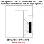
Magic smoke might just give you the munchies but a magic fold might be exactly what the doctor ordered! Xrk , were you the genius that came up with the Karlsonator fold? I have great respect for whomever devised it ... This is progress on the LAB15 (special) box , seems like this physical configuration is perfect for this cab .... Mild constriction travels around the top and upper right of the box (the port length is around 55cm @ 400 cm sq) , total path length is well over 180 cm(which was my goal).. Output down around 35hz is improved , only had to adjust previous sim a little bit to make it fit into this format..
I think th is one should work out in Akabak if someone is willing to give it a try ... will post more details and screenshots in a little bit 😀
Attachments
Last edited:
Magic smoke might just give you the munchies but a magic fold might be exactly what the doctor ordered! Xrk , were you the genius that came up with the Karlsonator fold? I have great respect for whomever devised it ... This is progress on the LAB15 (special) box , seems like this physical configuration is perfect for this cab .... Mild constriction travels around the top and upper right of the box (the port length is around 55cm @ 400 cm sq) , total path length is well over 180 cm(which was my goal).. Output down around 35hz is improved , only had to adjust previous sim a little bit to make it fit into this format..
I think th is one should work out in Akabak if someone is willing to give it a try ... will post more details and screenshots in a little bit 😀
If these are (close to) the final dimensions, I am delighted.
If these are (close to) the final dimensions, I am delighted.
BeauB,
These are very close, i even added the extra box volume to compensate for what the panels take up (3/4" ply) ... The driver is a tight fit, but it does fit .... Magnet ends up just inside the mouth but shouldn't stick out, great cooling & ventilation for the motor... Easy access to the driver ...
Port lengths, chamber, pipe areas and pipe lengths all seem to match up well between sim and sketch as far as i can tell and i reviewed the numbers a few times ..... I will want to go over everything again though, just to be sure ...
The other fold style wasn't cooperating with the sim well enough mainly due to the larger port area making things difficult, so instead I decided to try this ingenious Karlsonator style fold, but without expansion, and it seems to meet the requirements for our model perfectly 🙂 Cube-esque dimensions are nice too ..
Last edited:
Consider the thousands of EDM dance tracks with droning bass with as little as 3 dB dynamic range, same as a sine wave (the voltage Hornresp assumes), and that drone can occur where the impedance is at minimum, (often within 1/10th of an ohm of the DCR), and at the impedance minima, the excursion is also at minimum, so voice coil heating is at maximum.I use 1.5 as my multiplier but a more conservative figure to use would be 1.3, so in that case a driver with an RE of 3.5 ohms would be considered a 4.55 ohm driver, and thats the number you would punch into the "load impedance" field within HR's Eg popup window ...........
Anyway, the RE/Impedance multiply method thing sounds weird i know, and its already been covered once in this discussion so i don't want to sound repetitive or hounding like the cantankerous old coot that im trying hard not to become in my old age ....hehe
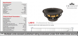
Now consider that most high power sub drivers are rated with the AES 426 compressed pink noise source, which has 6 dB dynamic range, only half the average power of the indicated rating, the 600 watt AES rated Lab 15 would be rated at 300 watts at it's impedance minima.
The Parts Express and the Ebay listings mistakenly substitute RMS for AES 426.
I don't consider either 1.5 or 1.3 multipliers to be conservative, unless the speaker is rated in watts RMS, (of course watts are watts, voltage can be peak or RMS...)
Art "conservative geezer" Welter
Attachments
Magic smoke might just give you the munchies but a magic fold might be exactly what the doctor ordered! Xrk , were you the genius that came up with the Karlsonator fold? I have great respect for whomever devised it ... This is progress on the LAB15 (special) box , seems like this physical configuration is perfect for this cab .... Mild constriction travels around the top and upper right of the box (the port length is around 55cm @ 400 cm sq) , total path length is well over 180 cm(which was my goal).. Output down around 35hz is improved , only had to adjust previous sim a little bit to make it fit into this format..
I think th is one should work out in Akabak if someone is willing to give it a try ... will post more details and screenshots in a little bit 😀
The Genius behind the Karlsonator fold is GregB. I just modeled it in AkAbak. Your sketch resembles the Karlasonator although you don't have an expanding pipe before the constrictor. A so called reverse TQWT MLTL 6th order bandpass with Karlson aperture is the full description.
Consider the thousands of EDM dance tracks with droning bass with as little as 3 dB dynamic range, same as a sine wave (the voltage Hornresp assumes), and that drone can occur where the impedance is at minimum, (often within 1/10th of an ohm of the DCR), and at the impedance minima, the excursion is also at minimum, so voice coil heating is at maximum.
Now consider that most high power sub drivers are rated with the AES 426 compressed pink noise source, which has 6 dB dynamic range, only half the average power of the indicated rating, the 600 watt AES rated Lab 15 would be rated at 300 watts at it's impedance minima.
The Parts Express and the Ebay listings mistakenly substitute RMS for AES 426.
I don't consider either 1.5 or 1.3 multipliers to be conservative, unless the speaker is rated in watts RMS, (of course watts are watts, voltage can be peak or RMS...)
Art "conservative geezer" Welter
I think i am being totally misunderstood on this topic, i am not suggesting anyone overpower their drivers, thats not what i am saying at all, but people keep interpreting it that way for some reason ......... I am just saying that it would be nice to actually deliver the power that you intended upon delivering, that's all, and i have a method that i have been using to get my voltages closer to some sort of accuracy so i can make proper comparisons in sim ... My method is not perfect but i think it definitely helps ..... I will try to explain more, and i am sorry if i sound repetitive at all ..
Art ,
I totally agree with you,
It is a good policy to stay conservative with the drive levels , especially with today's modern music production considering the high density of some tracks, the "Loudness wars" of modern producing, and as you say "droning" sustained bass sines that fall within the range of FB (minimum impedance and minimum displacement zones) etc.. Reproducing these tracks undoubtedly places brutal demands upon a voicecoil in the thermal sense ......
I absolutely agree....
I was in no way suggesting that we try to feed more wattage into these drivers than they are rated for, that would of course be a terrible idea ....
The "multiplier" that i speak of is not used to multiply the actual wattage, its just a multiplier applied to the driver's RE figure to come up with a more realistic load impedance that can be inputted into HR's Eg popup window in order to assist HR in calculating a more accurate voltage so we can actually deliver the INTENDED amount of power to the drivers (instead of less than the wattage figure that we typed into HR's Eg popup... ..... RE figures being in the high range = Less wattage delivered at same voltage )
I was only referring to DC resistance of the voicecoil (RE) and how it relates to wattage due to the current draw of the driver.. Thats all ... I just want to make sure that when i am doing simulations that i am actually giving the driver the appropriate amount of wattage in the model, especially when comparing different drivers in the same cab, or when comparing two cabs with different drivers because the two drivers may have significantly different RE figures but are still designated with a generic 8ohm or 4ohm impedance .......... The problem is that most drivers aren't EXACTLY 4 or 8ohms , but that (4 or 8) is what most folks seems to be inputting into HR's Eg popup when we should be using a much more specific impedance figure..... This is not HR's fault , it is just that the manufacturers of these drivers build their voicecoils with RE values that are absolutely all over the place ... It seems that the standards are pretty loose, and that can be misleading when performing comparative simulations where every decibel counts ...
I respect all of you guys here in DIYaudio tremendously ( i have learned so much from reading all of your discussions in these forums and i am greatly appreciative for all of it) and i really want you to know that i am not trying to be contrarian or argumentative about this, i just think that the issue does deserve some attention and (regardless) it is difficult to avoid the topic when someone points out that my model is a few volts off compared to their model and i have to explain why ... Then i get accused of abusing voice coils and someone calls VCPS on me (Thats Voice-Coil Protection Services) and my woofers have to go live with other people for a while...... 😉
Last edited:
The Genius behind the Karlsonator fold is GregB. I just modeled it in AkAbak. Your sketch resembles the Karlasonator although you don't have an expanding pipe before the constrictor. A so called reverse TQWT MLTL 6th order bandpass with Karlson aperture is the full description.
Is he still around? His fold style was an exceptional solution to making a physical manifestation of the HR sim for the Lab15(special) Ml-transflex ...It worked out perfectly as far i can tell ...Such a good match ... I cannot believe how easily everything just fell-into-place once i switched to that dual fold scheme ... I suppose i should let Greg know that i used it and say thanks to him ..
Getting ready to post more details on that box for BeauB here in a bit ..
Yes, Greg B is here and quite active in the forums and especially Fullrange forum. You should check out his image archive called "Stupid HiFi Tricks".
Before I even ran the sim with the scaled Karlsonator I knew it would work with the Lab15 - I have simulated probably more drivers in that alignment than anything (about 50 drivers) and almost all of them could be made to work with the right adjustment of height/depth and width. A driver with Qts from 0.35 to 0.65 works very well in it. Even high 0.9 Qts can work, albeit, larger volume but bot a problem for smaller 2 or 4 in fullrange drivers. Send Greg B a PM if you want him to see what you did with his design. Or post your ideas in the "Karlsonator" thread in Fullrange.
Last edited:
Yes, Greg B is here and quite active in the forums and especially Fullrange forum. You should check out his image archive called "Stupid HiFi Tricks".
Before I even ran the sim with the scaled Karlsonator I knew it would work with the Lab15 - I have simulated probably more drivers in that alignment than anything (about 50 drivers) and almost all of them could be made to work with the right adjustment of height/depth and width. A driver with Qts from 0.35 to 0.65 works very well in it. Even high 0.9 Qts can work, albeit, larger volume but bot a problem for smaller 2 or 4 in fullrange drivers. Send Greg B a PM if you want him to see what you did with his design. Or post your ideas in the "Karlsonator" thread in Fullrange.
Very cool, Thats a highly versatile design!
I will send a message off to Greg right away after i post this 🙂
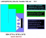
I made a Hornresponse correlated color key sketch for this Lab15(special) cab , check out the attachment ..... It made it colorful !

Attachments
The finishing touches on the LAB15(SPECIAL) CABINET
This is all of what i have so far for the newest and most refined version of the Constricted-Transflex cabinet or ML-TP , or series tuned and mass loaded 6th order bandpass for the LAB15(SPECIAL)... I need to settle on a name for the alignment and stick with it ...
This should hopefully be the final version ... I might only make a few minor tweaks to the HR inputs but other than that this is pretty much it ! (Unless one of the Akabak gurus spots some insurmountable problem with it, but that is unlikely , this box is fairly straightforward) ..
I think we may have a winner here for Eminence driver, but i don't want to speak too soon ! 😛 This has been a learning process ....
Thanks to GregB for this fantastic fold style!
I will probably put all of these sketches and screenshots (along with a little more data)together into a single patchwork collage jpeg so it is a single file ....
This is all of what i have so far for the newest and most refined version of the Constricted-Transflex cabinet or ML-TP , or series tuned and mass loaded 6th order bandpass for the LAB15(SPECIAL)... I need to settle on a name for the alignment and stick with it ...
This should hopefully be the final version ... I might only make a few minor tweaks to the HR inputs but other than that this is pretty much it ! (Unless one of the Akabak gurus spots some insurmountable problem with it, but that is unlikely
, this box is fairly straightforward) ..I think we may have a winner here for Eminence driver, but i don't want to speak too soon ! 😛 This has been a learning process ....
Thanks to GregB for this fantastic fold style!
I will probably put all of these sketches and screenshots (along with a little more data)together into a single patchwork collage jpeg so it is a single file ....
Attachments
-
 Lab15-Special-35hz-ML-TRANSFLEX-DOUBLE-FOLD-149L.jpg36.9 KB · Views: 279
 -
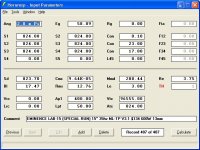 Lab15-Special-35hz-ML-TRANSFLEX-DOUBLE-FOLD-149L-INPUTS.jpg59.9 KB · Views: 262
 -
 Lab15-Special-35hz-ML-TRANSFLEX-DOUBLE-FOLD-149L-KEY.JPG41.3 KB · Views: 247
 -
 Lab15-Special-35hz-ML-TRANSFLEX-DOUBLE-FOLD-149L-RESPONSE-2CABS-HALFSPACE.jpg47.3 KB · Views: 254
Last edited:
This is all of what i have so far for the newest and most refined version of the Constricted-Transflex cabinet or ML-TP , or series tuned and mass loaded 6th order bandpass for the LAB15(SPECIAL)... I need to settle on a name for the alignment and stick with it ...
This should hopefully be the final version ... I might only make a few minor tweaks to the HR inputs but other than that this is pretty much it ! (Unless one of the Akabak gurus spots some insurmountable problem with it, but that is unlikely
I think we may have a winner here for Eminence driver, but i don't want to speak too soon ! 😛 This has been a learning process ....
Thanks to GregB for this fantastic fold style!
I will probably put all of these sketches and screenshots (along with a little more data)together into a single patchwork collage jpeg so it is a single file ....
Wow - as soon as we have a finalized, dimensioned drawing - I'll be at Ganahl buying wood.
Hi MMJ,
Not a problem 🙂. Thanks for making me aware of the issue.
Yes.
Kind regards,
David
Excellent! Thank you for looking into that David , i hope it wasn't too much hassle ...
Not a problem 🙂. Thanks for making me aware of the issue.
Will both the wiz and main have the popup with the "prompt" switch on?
Yes.
Kind regards,
David
I just want to make sure that when i am doing simulations that i am actually giving the driver the appropriate amount of wattage in the model
Hi MMJ,
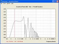
No matter what value of Eg you specify, the voltage will still be constant, which means that the electrical input power will vary significantly with frequency due to changes in the system electrical impedance. (Select Tools > Sample from the Acoustical Power window and move the frequency slider to see how much the electrical input power can change with frequency).
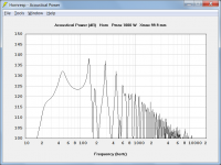
Constant electrical input power can however be specified in lieu of constant input voltage by using the Maximum SPL tool with Pmax set to the desired input power and Xmax set to 99.9 to prevent any displacement limiting. (The attached example shows the response for the design given in Post #531, assuming a constant input power of 1000 watts).
Kind regards,
David
Attachments
Hi MMJ,
No matter what value of Eg you specify, the voltage will still be constant, which means that the electrical input power will vary significantly with frequency due to changes in the system electrical impedance. (Select Tools > Sample from the Acoustical Power window and move the frequency slider to see how much the electrical input power can change with frequency).
Constant electrical input power can however be specified in lieu of constant input voltage by using the Maximum SPL tool with Pmax set to the desired input power and Xmax set to 99.9 to prevent any displacement limiting. (The attached example shows the response for the design given in Post #531, assuming a constant input power of 1000 watts).
Kind regards,
David
This, is what I was trying to say all along 🙂.
Also, MMJ, should the simulations of the pipe and reverse taper variants be using the TH methodology or the ND? I'm not sure what mounting style qualifies for both as it seems to look the same mounting wise as your MLTP with you use TH mounting yet your pipe simulations use ND.
Hi MMJ,
No matter what value of Eg you specify, the voltage will still be constant, which means that the electrical input power will vary significantly with frequency due to changes in the system electrical impedance. (Select Tools > Sample from the Acoustical Power window and move the frequency slider to see how much the electrical input power can change with frequency).
Constant electrical input power can however be specified in lieu of constant input voltage by using the Maximum SPL tool with Pmax set to the desired input power and Xmax set to 99.9 to prevent any displacement limiting. (The attached example shows the response for the design given in Post #531, assuming a constant input power of 1000 watts).
Kind regards,
David
I know that you and Mr Sabaspeed are right about that, the impedance changes radically through the usable range and current draw is associated with that impedance so electrical input (wattage) is also following those same radical curves in an inverse tracking fashion..... I totally get that part and i totally agree with you guys on it .....
I guess i am just looking for a more valid reference for calculating voltage ....
Between different makes and models of drivers the RE varies so much it seems to me that the manufacturer's generic label of 4 ohm or 8 ohm isn't specific enough ... Although i do acknowledge that there is probably more to determining a driver's impedance rating than just it's RE, it hasn't stopped me from trying to "roll my own" impedance figure for the purpose of inputting that figure into the Eg's voltage calculation popup window, (I do this however with the understand that the way i derived this impedance figure is likely oversimplified because ideally other factors like reactance should also be taken into account , right? ...So it is just an approximation ....
Nevertheless i think that the impedance figure that i am coming up with is at least more accurate than the generic "nominal" impedance that the manufacturers give us , and that helps me more accurately create the equivalent voltages for comparison's sake in simulations ....
So for example, instead of just plain 4 ohms we could consider a driver like The Eminence BP102-4 (referred to in post #498) to have an impedance of 3.78 ohms which is pretty darn close to 4 ohms , so a person might say: "whats the big deal?!?" right? The problem is that using the same standard (RE*1.4) implies that the Eminence Legend 620H is a 5.5 ohm driver, even though both drivers are labeled by Eminence as "4 ohm" and this can cause comparative simulations to be misleading if inputs are done in the standard way (by using the generic 4 ohm figure to calculate voltage)..
In AkAbak I plot the electrical power vs freq at a fixed voltage and you can see how that changes. Then set the peak power to match ratings by adjusting voltage. That is max voltage. Takes impedance changes and Re into account.
This, is what I was trying to say all along 🙂.
Also, MMJ, should the simulations of the pipe and reverse taper variants be using the TH methodology or the ND? I'm not sure what mounting style qualifies for both as it seems to look the same mounting wise as your MLTP with you use TH mounting yet your pipe simulations use ND.
Hey there Saba ,
Reverse taper designs can be created as either tapped or not .... Either way can be made to work , generally the tapped version will allow a box size reduction but it may come at a cost of slightly reduced SPL... Sometimes a bit of tapped effect helps , sometimes it hurts , depends on the situation really ....
You can use any of the modes in Hornresponse to design reverse taper alignments, i would most often use OD or TH mode for something like that though because that allows having an offset driver, which is how most of my cabinets end up being configured , even if the driver offset is only half of the driver's diameter (because the woofer is loaded into the side at the end of the pipe)
ND and CH modes model the driver as being plugged in to the absolute end of the pipe with no offset whatsoever...
Reverse tapers work the same way that Mass Loading , mouth shading, ports and constrictions work to reduce physical path length.... Bass doesn't care whether or not you accomplish that in steps or if you do it in a long slow constriction .... With the absolute extreme being a Bass Reflex box (but at THAT extreme there is not nearly enough path length to provide any useful quarter wave action, so performance suffers, and the moral of the story is that you only want to take these path length reduction schemes so far ..... too much of a good thing can definitely be a bad thing , so find your "happy place" 🙂 )
In the ML-Transflex for the Lab15(special)we have just a bit over 6 feet of path length for a 35hz box , so the path is just moderately shortened which gives us great performance in a tidy package 🙂 Its a great balance of compromises, its that "happy place" i mentioned earlier ..😀
In AkAbak I plot the electrical power vs freq at a fixed voltage and you can see how that changes. Then set the peak power to match ratings by adjusting voltage. That is max voltage. Takes impedance changes and Re into account.
XRK,
That sounds pretty reasonable, so if i am understanding correctly does that mean that the lowest impedance that can be found within the sim's working range would be the defining factor when you are calculating voltage(to match with the rated power)?
Last edited:
XRK,
That sounds pretty reasonable, so if i am understanding correctly does that mean that the lowest impedance that can be found within the sim's working range would be the defining factor when you are calculating voltage(to match with the rated power)?
That's one way to do it. I just sweep the impedance curve, give like a 10-20% buffer and then use that. Most subwoofers have an impedance low spot of darn close to Re. E.G. 7.1 vs a Re of 7 for one of the designs I considered. But I consider it 8 for finding a starting voltage because there are some frequencies with significantly higher impedance. My reasoning is that any bass note with exactly Fs will have a spread of power plus or minus about 3-4 Hz at the least and thus an average impedance will help find the average impedance at the speaker. If you're running sine waves at FS or play certain genres you may just want to be a little more careful, but most subwoofers rated for 500 watts rms have no problem peaking in the 600-700 range so long as excursion is kept in check (and Xmech for sws12d4 is like 25 mm 1 way so I'm not worried about that) they just can't dissipate more than an average of 500 watts at the voicecoil for extended periods of time.
I'm sure most of this you already knew or suspected but I thought I'd mention it.
- Home
- Loudspeakers
- Subwoofers
- New sub design? Constricted Transflex, simple build (series tuned 6th order)