I'm repairing a Jands j700 power amp that has two different driver boards,one with DC Offset circuit and one without,so I'm going to build another DC Offset circuit for the missing one but the controlling op-amp BiMos CA3160e is not made anymore.It is 4mhz,I can get a BiMos CA3140 that is nearly identical except that it is 4,5mhz? Would it be possible to use this as a sub?
Maybe yes but maybe not, it will depend on circuit details. The CA3160 has a CMOS output stage meaning it'll swing from rail to rail. The CA3140 has a bipolar output stage so can't swing very close to the supplies.
Maybe yes but maybe not, it will depend on circuit details. The CA3160 has a CMOS output stage meaning it'll swing from rail to rail. The CA3140 has a bipolar output stage so can't swing very close to the supplies.
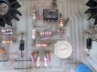
I did some more googles and found a sub for the CA3160e, its an AD820 apparently? So Ill order a few of those and see how it goes? Those caps in the offset circuit are all 10 nano-farads and the zener is 6.8volts.
Attachments
Last edited:
Looks like a good substitute which includes the rail-to-rail output. Just doesn't have the MOSFET input stage, though there's little doubt that JFETs will be totally fine in this application.
Looks like a good substitute which includes the rail-to-rail output. Just doesn't have the MOSFET input stage, though there's little doubt that JFETs will be totally fine in this application.
Thanks for for the help mate! It feels so much better when someone else has a look at it too instead of me blindly experimenting LOL cheers,🙂
Anyway I suggest you draw the schematic of the DC Offset (DC servo?) circuit and post it.
Much better than trying to read PCB values from a picture 😉
I *guess* that maybe the Op Amp used is not *that* critical, probably does not need rail to rail capability, not so sure about input impedance and offset, but seeing the circuit sure will help.
🙂
Much better than trying to read PCB values from a picture 😉
I *guess* that maybe the Op Amp used is not *that* critical, probably does not need rail to rail capability, not so sure about input impedance and offset, but seeing the circuit sure will help.
🙂
Hows this?Anyway I suggest you draw the schematic of the DC Offset (DC servo?) circuit and post it.
Much better than trying to read PCB values from a picture 😉
I *guess* that maybe the Op Amp used is not *that* critical, probably does not need rail to rail capability, not so sure about input impedance and offset, but seeing the circuit sure will help.
🙂
Attachments
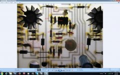
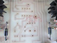
Those are good photos, but not a schematic.
A schematic shows the electrical relationship of the parts in a circuit. A wiring diagram (which is what your photos essentially are) shows the physical or mechanical relationship between the parts. Each is valuable, but they do different jobs.
A schematic shows the electrical relationship of the parts in a circuit. A wiring diagram (which is what your photos essentially are) shows the physical or mechanical relationship between the parts. Each is valuable, but they do different jobs.
The AD820 seems to be the right sub so Ill try that when it gets here.If it doesn't work, Ill figure out how to draw a schematic and post it. There is no service manual or schematic for this amplifier according to the manufacturers(Jands)
I'm repairing a Jands j700 power amp that has two different driver boards,one with DC Offset circuit and one without,so I'm going to build another DC Offset circuit for the missing one but the controlling op-amp BiMos CA3160e is not made anymore.It is 4mhz,I can get a BiMos CA3140 that is nearly identical except that it is 4,5mhz? Would it be possible to use this as a sub?
I did a little googling and found CA 3160E chips for sale on the web, including a number of eBay sources.
So here is a dilemma - what is better, a chip sold as being an exact replacement that may or may not be what it is claimed to be, or a different chip with similar but obviously exactly not the same properties?
Presumably the Jands power amp would have sufficient value when restored to health that you have a few dollars to fund some experimentation...
In general, the difference between a 4 mHz and a 4.5 mHz semiconductor would be inconsequential in any well-designed audio circuit.
Looking at the PCB photos, you do NOT want a fast opamp, it would oscillate.
The resistors around the opamp are fairly high value, hence the original choice of the bimos part.
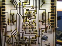
What are the actual supply voltages on the chip?
It looks like this may be a single supply circuit, the CA3160 worked with input down to the negative rail. No sign of connection to strobe or offset null
The resistors around the opamp are fairly high value, hence the original choice of the bimos part.
What are the actual supply voltages on the chip?
It looks like this may be a single supply circuit, the CA3160 worked with input down to the negative rail. No sign of connection to strobe or offset null
Last edited:
- Status
- Not open for further replies.
- Home
- Design & Build
- Parts
- Op-Amp substitute