To me your 0dBfs FFT looks anything but clean. It'd be okay if the result was dominated by 2nd and 3rd order, but the presence of the higher orders do bother me. Granted the -60dBfs looks a lot better, but they always tends to. How does the DAC perform at -1dBfs, -3dBfs, -5dBfs and -10dBfs? Also how does the distortion change with frequency?
OK, typically the absolute accuracy of the last few LSB's in an R2R DAC are not very important. Did you think of doing a basic analysis, maybe by Monte Carlo, and have a gradation of resistor tolerances with only a few at .01%. There must be a sweet spot in terms of cost performance. Number 2 have you thought of using some lower bits in an auto cal sequence to smooth some of the higher LSB major carries? The fact that your THD spectrum has a fairly flat amplitude would indicate impulsive errors as the boundaries are crossed.
You're correct on that, and I have actually done some thinking about it, ended up having the resistors for the 14 MSB bits be the best precision ones, with the 13 LSB bits be one grade less precise, like the 0.02% version have 0.05% resistors on the 13 LSB bits, to keep cost down but still having great performance when using the digital volume control. Could in principle use less and less precise parts going down on the bits, but it's again a question about not having too many different almost alike parts. Give an EMS provider an opportunity to mess up and they will take it....
The prototypes have 0.05% ones on the 14 MSB bits, with 0.1% ones on the 13 LSB bits.
And I really should do some Monte Carlo analysis, but as I'm not a serious math guy I'm just using gut feeling as guide for now 🙂
To me your 0dBfs FFT looks anything but clean. It'd be okay if the result was dominated by 2nd and 3rd order, but the presence of the higher orders do bother me. Granted the -60dBfs looks a lot better, but they always tends to. How does the DAC perform at -1dBfs, -3dBfs, -5dBfs and -10dBfs? Also how does the distortion change with frequency?
I'm perfectly happy with each harmonic being around -100 db down on the prototype with 0.05% resistors.... And most DAC's actually look worse at -60 db than at -1 db.
The DAC is FAST, I have 200 nS rise/fall time when doing 10 Khz square waves with output filter removed. So the linearity over frequency I expect to be great, although I haven't measured it yet, mostly because of measuring equipment limitations....
But that's actually the principle itself, the R-2R dac is only monotonic to the precision of the R-2R network, the tiny errors show up as what you could call "higher harmonic noise". The advantage of the sign magnitude DAC is then that the harmonics does down with the signal level, unlike a regular R-2R DAC.
I would love to see some FFT plots from a Burr-Brown colinear DAC, like the PCM63 or PCM1704 (colinear is their marketing name for sign magnitude).
Just remembered something about input protection diodes on the LME49710 buffers, so I lifted the pin so there is nothing at all on the output of the R-2R resistor network, except my scope.
10%/90% Rise/Fall times on a 10 Khz square wave is actually 70 nS....
10%/90% Rise/Fall times on a 10 Khz square wave is actually 70 nS....
I'm perfectly happy with each harmonic being around -100 db down on the prototype with 0.05% resistors
I'd be happy with the 2nd and 3rd harmonic lying at -100dB, and then for the level to decline with rising order, but not with you're getting. This is why I was asking what -1dB, -3dB etc look like. Clearly the harmonics go by the time you get to -60, but how far down to you have to go for them to go? All harmonics lying at -100dB isn't a problem imo at 0dBfs, if most of them fall off the chart when the input level falls a little.
.... And most DAC's actually look worse at -60 db than at -1 db.
Most good DACs tend to show nothing but noise with a -60dB signal.
I'd be happy with the 2nd and 3rd harmonic lying at -100dB, and then for the level to decline with rising order, but not with you're getting. This is why I was asking what -1dB, -3dB etc look like. Clearly the harmonics go by the time you get to -60, but how far down to you have to go for them to go? All harmonics lying at -100dB isn't a problem imo at 0dBfs, if most of them fall off the chart when the input level falls a little.
Most good DACs tend to show nothing but noise with a -60dB signal.
That's how it works with sign magnitude R-2R DAC, the errors due to the DAC being not monotonic at some level shows up as random harmonics and follow the level down. With the 0.05% resistors I was expecting higher levels harmonics, so I'm very happy with what I see on the FFT's, even as I don't trust my EMU-0404 much.
If you want it better, get the one with more precise resistors.
If you still don't like it, get a delta sigma DAC, we all agree that they measure much better.
In the end it all comes down to listening tests, not measurements, but I'm not there yet.
I'd like to connect raw output and on-board balanced output simultaneously. It can let me choose two different style sound. Is it okay?
I'd like to connect raw output and on-board balanced output simultaneously. It can let me choose two different style sound. Is it okay?
Yes.
If you want it better, get the one with more precise resistors.
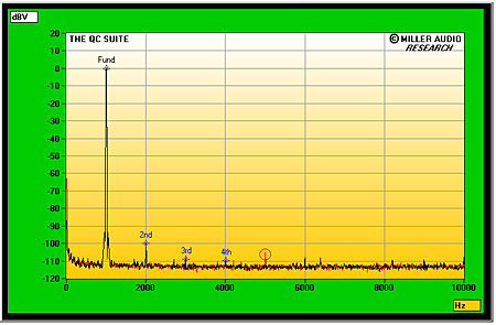
Here's an FFT from a CD player with the PCM1704K, it appears to measure superbly. No doubt it's internal resistors are trimmed to very tight tolerances, but is this the kind of performance gain that you would expect to see by using 0.01% resistors?
If you do not know the extent of how your sound card performs then you can run a loop back test, at the very least, to get an idea. Lots of ADCs in sound cards actually perform better if you feed them a signal that's a couple of dBs below their maximum amplitude.
In the end it all comes down to listening tests, not measurements, but I'm not there yet.
I'd agree that listening is the ultimate arbiter, however in listening R2R based DACs don't normally turn out to do as well as segmented current source designs. I have a hypothesis that this is due to R2R having higher glitch energy. Scott has mentioned that the harmonics of your THD FFT don't fall off much with frequency and this is an indicator of glitching - glitches have high HF energy. Glitching in an R2R DAC is mainly a function of timing mismatches between the switches.
oversampling up to maybe 3.072 Mhz
Does this improve the specs?
Hi Soekris,
Please accept the question of a noob: I checked the Nichicon CL serie to try to understand the needs in such a design. My first understanding is you need a very low inductance. Then trying to look for the ESR of the 80 uF/16 V (820 C voltage code) caps of your photograph, I did'nt see some 80 uF cap in the Datasheet on the Mouser PDF nor I was capable to check it on the Nichicon website.
My question is : does such a design in relation to a more classical DAC needs very low ESR if osciliation are avoided in the PS design ? Does the digital section or your embeded LME buffer need such very low ESR for subjective listening improvement (not talking about caps soup but just talking of any possible empirical difference which can be heard and of course if checked before with theory & scope).
Looking at the ESR of the nearer value (100 uF), I mean the ESR is around 20 to 25 M ohm : could it be an improvement to go to a 821 16 C = 820 uF/16V with the same simplicity you talked about simple little torroid (or R-Core) ?
Sorry for the too simple question in relation to the high level of this thread...just want to understand if ESR is important in relation to the high level of such designs.
I'm defintly interrested as the output filter seems to be programmable and has a great importance of the subjective listening result with the Delta Sigma designs... in any case that's my simple understanding.
thanks, forgett it if not important or OT .🙁
Last edited:
Here's an FFT from a CD player with the PCM1704K, it appears to measure superbly. No doubt it's internal resistors are trimmed to very tight tolerances, but is this the kind of performance gain that you would expect to see by using 0.01% resistors?
If you do not know the extent of how your sound card performs then you can run a loop back test, at the very least, to get an idea. Lots of ADCs in sound cards actually perform better if you feed them a signal that's a couple of dBs below their maximum amplitude.
I have done loopback, with varying results depending on settings, and my EMU-0404 have that spike at 30 Khz some claim is due to it's switching power supply.
It looks like the pcm1704 have the same kind of harmonics, just 110 db down and covered by noise.... My DAC has way less noise so it looks worse.
If theory, going from 0.05% to 0.01% should improve by 14 db, but I have no clue how much better the resistors are in practice until I have a board with 0.01% parts. Which I have decided make a few of in the first batch so I can get more data, just purchased 2 x 1000 pcs 0.01% parts from Digikey....
I'd agree that listening is the ultimate arbiter, however in listening R2R based DACs don't normally turn out to do as well as segmented current source designs. I have a hypothesis that this is due to R2R having higher glitch energy. Scott has mentioned that the harmonics of your THD FFT don't fall off much with frequency and this is an indicator of glitching - glitches have high HF energy. Glitching in an R2R DAC is mainly a function of timing mismatches between the switches.
There are probably tiny glitches, can see a little sometimes on my scope, the LVC595 is the fastest shift registers I can get, and I also haven't optimized timing in the FPGA yet (put constrains on the clock signal), might be a little to gain there.
Yes same here, I was just curious if the 3.072 MHz interpolation improves THD, IMD, time etc.
Much like Eldam is not aware of capacitors, I am not very aware of how that interpolation affects a 24-bit discrete, however I lean towards that it will provide slightly better sonics.
I saw someone ask about Rhopoint resistors, well, if resistors have been analyzed with a parameter like THD or esoterik lattice vibrations, I am not aware.
For capacitors you can look up Cyril Bateman.
Bah, if good for medical or spaceships... Resistors - Components : wirewound, smd, temperature, all you dreamed if money (my understanding they were buyed by Vishay precision grup !)
But sure OP does be right about the good enough performance of Npos in relation to the price & in relation to the big quantity needed in one Dac ! Thanks for cap's Cyril Bateman input: 'll google it ! I like two cents questions as it allows sometimes the best technicians to beam on more serious & smartest questions 🙂
But sure OP does be right about the good enough performance of Npos in relation to the price & in relation to the big quantity needed in one Dac ! Thanks for cap's Cyril Bateman input: 'll google it ! I like two cents questions as it allows sometimes the best technicians to beam on more serious & smartest questions 🙂
soekris,
Very interesting, subscribed.
Didn't find any information on listening tests in the thread. What would you say about the sound quality if to compare with top delta-sigma? Is there any fundamental audible differences?
Thanks.
Very interesting, subscribed.
Didn't find any information on listening tests in the thread. What would you say about the sound quality if to compare with top delta-sigma? Is there any fundamental audible differences?
Thanks.
Gentlemen (and ladies if present), we can discuss the minutia of signal distortion in this circuit ad nauseum. Until Søren (that's his name by the way, not soekris) does a discrete listening test as suggested above with a top of the line DAC, we should wait with further comments.
Please hurry Søren, can't wait for the results!
Please hurry Søren, can't wait for the results!
Yes, We need a ABX blind test, please send me an unit: you can put on the package your real name or your avatar discrete r2r one 🙂 with the precision you wisch !
Last edited:
Yes same here, I was just curious if the 3.072 MHz interpolation improves THD, IMD, time etc.
Not directly. Oversampling may, however, indirectly reduce IMD by moving the ultrasonic image bands up in frequency by a factor equal to the oversampling ratio, where they can be more easily filtered so to not provoke succeeding gain stage misbehavior.
In addition, if I correctly recall my DSP theory, oversampling will spread the quantization noise power flatly over the oversampled spectrum, thereby reducing the quantization noise within the audio band. Each doubling of the native sample rate via oversampling reduces the quantization noise power by 3dB, as I recall. So, for example, an x8 oversampling would theoretically reduce quantization noise power by 9dB. However, I'd have to check my technical references to be certain. This effect is related to, but not the same as noise shaping, which does not distribute the quantization noise flatly across the oversampled spectrum.
Hi Soekris,
Please accept the question of a noob: I checked the Nichicon CL serie to try to understand the needs in such a design. My first understanding is you need a very low inductance. Then trying to look for the ESR of the 80 uF/16 V (820 C voltage code) caps of your photograph, I did'nt see some 80 uF cap in the Datasheet on the Mouser PDF nor I was capable to check it on the Nichicon website.
My question is : does such a design in relation to a more classical DAC needs very low ESR if osciliation are avoided in the PS design ? Does the digital section or your embeded LME buffer need such very low ESR for subjective listening improvement (not talking about caps soup but just talking of any possible empirical difference which can be heard and of course if checked before with theory & scope).
Looking at the ESR of the nearer value (100 uF), I mean the ESR is around 20 to 25 M ohm : could it be an improvement to go to a 821 16 C = 820 uF/16V with the same simplicity you talked about simple little torroid (or R-Core) ?
Sorry for the too simple question in relation to the high level of this thread...just want to understand if ESR is important in relation to the high level of such designs.
I'm defintly interrested as the output filter seems to be programmable and has a great importance of the subjective listening result with the Delta Sigma designs... in any case that's my simple understanding.
thanks, forgett it if not important or OT .🙁
Those ARE 820uF 16V CL series, markings are Nichicon's own codes.... Low ESR types are needed for the RC filter feeding the LME, not really for the main rectifier capacitors, but I mostly use low ESR types anyway, price difference is small nowadays.
The DAC reference voltages are two step, first to +- 5V, then to +-4V by precision low noise medium current opamps, I couldn't find any power supply chips that fit....
The LME output buffers are powered via an additional large RC filter after the main capacitors, no active regulators. With a typical PSRR of 125 db I didn't worry much about 100/120 hz ripple, only worried about higher frequency noise on the power rails....
A careful design of the whole power supply is needed for optimal sound, and for a voltage output discrete DAC the reference are very critical, more than for integrated chips as those are mostly current output.
- Home
- Vendor's Bazaar
- Reference DAC Module - Discrete R-2R Sign Magnitude 24 bit 384 KHz