Dear All:
Do you know how to calculate the max power dissipation of the OPA2134 with the SOIC-8 package.
I have calculated Power dissipation of 220mW per channel with these parameters:
Vcc: 18v (-9v to +9v)
Vpeak: 4v
Rload: 100 Ohm
Max current x channel = 40ma.
Regards.
Alfedo Mendiola Loyola
Lima, Peru
Do you know how to calculate the max power dissipation of the OPA2134 with the SOIC-8 package.
I have calculated Power dissipation of 220mW per channel with these parameters:
Vcc: 18v (-9v to +9v)
Vpeak: 4v
Rload: 100 Ohm
Max current x channel = 40ma.
I calculated by myself the Max Dissipation:
JA max = 150*
TA= 25*
R Theta JA = 150*/w
Max power dissipation: 0.83 W = 833 mW.
JA=Junction Temp
TA= Ambient Temp
R Theta JA = Thermal Resistance
PDmax = ( TJmax - TA ) / R Theta JA
Regards.
Alfedo Mendiola Loyola
Lima, Peru
Last edited:
With an output of 4V and a supply of 9V, passing 40mA the chip will be dissipating 200mW.
Also note that the max current the chip can handle is 35mA, current is internally clamped at 40mA.
Is this for a headphones amplifier? Cmoy is a really bad design.
Also note that the max current the chip can handle is 35mA, current is internally clamped at 40mA.
Is this for a headphones amplifier? Cmoy is a really bad design.
With an output of 4V and a supply of 9V, passing 40mA the chip will be dissipating 200mW.
Also note that the max current the chip can handle is 35mA, current is internally clamped at 40mA.
Is this for a headphones amplifier? Cmoy is a really bad design.
Yes is a Custom Cmoy Design for Headphones.
I can't find the max dissipation of the OPA2134 for SOIC-8 in the DataSheet.
Regards.
Alfredo Mendiola Loyola
Lima, Peru
2134 is a very bad choice for Cmoy, which is a very marginal design.
Many op amps can drive low impedance headphones directly, but they will not come close to meeting their performance specifications in this circuit. Op amp specifications are typically rated into a 600 ohm load, and there is no easy way around this without some kind of buffer.
Many op amps can drive low impedance headphones directly, but they will not come close to meeting their performance specifications in this circuit. Op amp specifications are typically rated into a 600 ohm load, and there is no easy way around this without some kind of buffer.
2134 is a very bad choice for Cmoy, which is a very marginal design.
Many op amps can drive low impedance headphones directly, but they will not come close to meeting their performance specifications in this circuit. Op amp specifications are typically rated into a 600 ohm load, and there is no easy way around this without some kind of buffer.
Won't I be able to load 64 Ohm headphones using the OP2134 with Cmoy?
I didn't know that.
What is the minimum load that a OPA2134 can source?
Regards.
Alfredo Mendiola Loyola
Lima, Peru
Don't forget to add the chip quiescent current to your package dissipation calculations. The OPA2134 is listed as Iq = 4ma typical, but that is per amplifier and your chip has 2. With +/-9V rails the quiescent current adds (2 * 4mA) * [9V - (-9V)] = 144mW of power dissipation. That already is about half of the 300mW or so that SOIC-8 packages can dissipate.
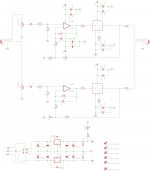
I will test this Opa2134 with a Buffered output using a BUF634.
This schematic is based on the Pimeta V1 .
I hope it works well.
Regards.
Alfredo Mendiola Loyola
Where did you get that circuit? It looks good; I like the nested feedback.
I would configure it for unity DC gain.
What is the minimum load that a OPA2134 can source?
According to the datasheet, I believe it is 600 ohms.
Many op amps will drive significantly lower impedance loads, with reduced performance. If you load a 2134 with a low impedance load, you will lose most of the benefits of this fine op amp. A lowly 5532 would most likely provide better performance driving a set of cans.
Using a buffer will get the maximum performance from a 2134.
Where did you get that circuit? It looks good; I like the nested feedback.
I would configure it for unity DC gain.
According to the datasheet, I believe it is 600 ohms.
Many op amps will drive significantly lower impedance loads, with reduced performance. If you load a 2134 with a low impedance load, you will lose most of the benefits of this fine op amp. A lowly 5532 would most likely provide better performance driving a set of cans.
Using a buffer will get the maximum performance from a 2134.
I made the circuit based on the PimetaV1 project and I improved it with better resistor values...
I made the circuit based on the PimetaV1 project and I improved it with better resistor values...
Did you use the 2134 and 634?
Good work.
Did you use the 2134 and 634?
Good work.
Yes, I used the OP2134 and the BUF634.
I would like to use OPA627 but I would have to change some resistors on the inner feedback.
Alfredo Mendiola Loyola
Lima, Peru
- Status
- Not open for further replies.
- Home
- Amplifiers
- Headphone Systems
- Opa2134 Max. Power dissipation