Conspiracy theories.
I am very surprised people don't speculate about the LHC. My Swiss friend Pius asked me in a way that suggested fear what it was about? As I honestly don't know I said it is a caprice. I went on to say the skills will help build fusion reactors. Joy of joys I am right. The people moved to JET and now to the bigger project in France under Steve Cowley. Now the crunch. If fusion had the money of the LCR it probably would work right now. The minimum size is 1 gigawatt. That's a third of the size of coal fired Didcot just closed so why not? Didcot is about 4 miles from JET and the Diamond light source. LHC is painted Oxford blue. No accident. speaking of which I think fusion reactors stop being dangerous 15 minutes after a breach.
The previous LHC director who's name I forget said Margret Thatcher was too stupid to understand his work (he wrapped it up differently by saying she would not have been able to be a science minister, look up her CV if wondering, I think the word chemistry told him she was too stupid). I strongly doubt that. She knew too well is my guess? What a git. She was bonkers and that's not so unusual in her job. Mr Tony B?
LCR is data in search of applications. Hi fi is applications in need of data.
Back to planet Earth.
I attached a schematic I’d like some opinions on.
To the left, diagram Case 1, shows what we are all familiar with, a simple differential pair. Arbitrarily, I used 2n5551 trannies, for no particular reason other than a simple illustration. The power lines of +/-50V however were chosen on purpose.
Case 1
Same as base, but I added a 47 Ohm resistor R3 and followed it with a 220uF/63V capacitor before reaching the differential pair. Its cut-off point should be around 30 Hz. My question is this: should I expect to have cleaner to much cleaner power on the collectors of the trannies, and are there any unforeseen issues which may arise that I don’t see, and I see none except increased cost?
Case 2
Same as Base, but this time we have two 1N4148 diodes between the collectors and the resistors. This is a frequent trick used in Marantz amps for some 30+ years now. What is the point? To isolate the collectors from the PSU line? To slightly raise the current draw of the next stage? Both?
Case 3
Similar to base, but now with 2SK170 FETs. They are rated at 40V, so obviously I need to do something since I have 50V coming in. I could construct a small local regulator to tame the voltage, or I could construct a cascode, which would be my first instinct response. But sticking in two 30V zeners on both FETs will do the same thing in a much simpler way. I have seen a lot of this in many German schematics, but never anywhere else. What’s the problem? Am I introducing too much Zener noise?
Case 4
A combination of Cases 2 and 3, plus an elaborated CCS. Given that the gain set by emitter resistors for the stage is just less than 10:1, what could I hope for? An ultra linear, ultra low noise input stage? In which about the only tuning could be replacing 2N5551 with 2SC2240?
Opinions welcome, ideas even more so.
Attachments
What about a single resistor and ultra ripple free PSU? Try a PP3 battery at first with small filter cap. The input stage has a very small voltage swing as it is clamped by the VAS stage. It will not be climbing that resistor much and the curve distortion is irrelevant. You could have a 200 V supply and one resistor if wanting it to be a gentle curve. Other people do differently to me as they do the usual thing.
When someone brought this up the single resistor had about 96dB rejection compared with 127 dB if the LED version. As we all agreed the CCS is cheap and why not. Why not is fine if we know the alternatives as choices and not doctrine. One guy said something very wise. At HF the CCS is no better than a resistor and that is when we need it most.
If you want ultra low noise then 6 devices is good. Will get about root 2 reduction. Use my 2 x 1K I showed before in ultra simple amp with optional bootstrap between feedback path and the +ve input. 2SA1085?
About conspiracy theories . I am saying much of hi fi folklaw is similar. Planet Earth or not the mind set of people is curious.
What about a single resistor and ultra ripple free PSU? Try a PP3 battery at first with small filter cap. The input stage has a very small voltage swing as it is clamped by the VAS stage. It will not be climbing that resistor much and the curve distortion is irrelevant. You could have a 200 V supply and one resistor if wanting it to be a gentle curve. Other people do differently to me as they do the usual thing.
When someone brought this up the single resistor had about 96dB rejection compared with 127 dB if the LED version. As we all agreed the CCS is cheap and why not. Why not is fine if we know the alternatives as choices and not doctrine. One guy said something very wise. At HF the CCS is no better than a resistor and that is when we need it most.
If you want ultra low noise then 6 devices is good. Will get about root 2 reduction. Use my 2 x 1K I showed before in ultra simple amp with optional bootstrap between feedback path and the +ve input. 2SA1085?
About conspiracy theories . I am saying much of hi fi folklaw is similar. Planet Earth or not the mind set of people is curious.
Nige, have you considered, or better yet, actually tried to construct your CCS as a cascoded pair?
If memory serves, cascodes tend to be very wide bandwidth, more so than any single transistor.
JET FET in might be excellent. Mostly the bandwidth is good. The hiss of the emitter resistors is a problem in your design . I was given a rather daft but plausible reason .Tubes have a pinker noise spectrum and transistors blue. The blue can only be offset by being non existent. I would say the blueness refers to the partition in the transistor somewhat like a pentode (pure guess). Bad pentodes like USSR EF86 were very blue themselves and Mulllard pink.
The CCS cascode pair is great if there is a real problem. That is no good reason to reject it. 4 valves per cylinder was sold with iron piston engines in the 1930's. I approve as the iron piston will expand instep with the barrel and 4 valves was for boasting. Even today most engines do not need 4 valves. The advantage seems to be they pass emissions better when fitted. Kawasaki always had more horsepower with 2 valves than the 4 valve others. In the end they gave in.
To my simple mind noise be it ripple ( or worse ) and hiss are the questions. Linearity is not. The input pair as a non degenerated JFET will possibly excel in all ways possible. Also no feedback arm capacitor need as a JFET needs almost no current and 100% DC feedback not required. As you use a servo even better reason. JFET should allow higher resistance input without noise penalty for the same reasons. You might have to play with VAS degeneration to win back a result like you use right now. My crude guess is -6 dB noise for same performance if you dispense with LTP degeneration. JFET has high internal degeneration anyway and thus lower gm. Swings and roundabouts you might win.
Sorry to bang on about engines. My new mower is OHV and the old ones were side valve. I suddenly realized it must be emissions. My previous one in 16 years did 200 hours. The world has gone mad. I want side valve. The new one drinks petrol just as fast. Drink being the right word. 5W30 synthetic working well. Thanks everyone who advised.
R3 C1is a nice idea if the dynamic range is available to VAS input. Why no current mirror?
Last edited:
Sorry I missed your point about that . Which is ? Both have written thing that make me think in a different direction than the self anointed experts for that I am beholding to both . 🙂Both Richard and John. ...The writings are on the tablets of the Internet, for million years to come ...
I found that the ABX method was more a 'trick' of the mind
John, it's not really a trick. The difference in perception between 'open' and controlled listening is well known and explainable, for maybe at least the last 100 years. Google 'psycho-acoustics'😉
Jan
My sources differ with your sources.
Must... resist... obvious... answer...
I am always surprised how often people who don't know about wine get it wrong. Unfortunately that is a vast market. The truth is the truth of the masses. That is the truth we must never forget. Ivory towers and all that.
I said to some guy " can you honestly say that isn't like live music". To which he said " you are assuming I can face live music when home from work" . Good point I think. I showed a very good listener the Naim CD player when it was first on the market. We listened to Maria Calas 1953 Belini. When I protested that the Arcam machine was less accurate as I could no longer hear scrape flutter on the master-tape she said " that's exactly what I don't want to hear" . I protested if it is there it is there. She bought the Arcam which was expensive , I was pleased and sad as I knew she could afford the Naim.
I said to some guy " can you honestly say that isn't like live music". To which he said " you are assuming I can face live music when home from work" . Good point I think. I showed a very good listener the Naim CD player when it was first on the market. We listened to Maria Calas 1953 Belini. When I protested that the Arcam machine was less accurate as I could no longer hear scrape flutter on the master-tape she said " that's exactly what I don't want to hear" . I protested if it is there it is there. She bought the Arcam which was expensive , I was pleased and sad as I knew she could afford the Naim.
Nigel, using FETs for input is fine, but do remember, single package dual FETs matched to a reasonable degree are becoming as rare as wisdom teeth. Therefore, the degeneration resistors also serve as additional matching, a point not to be missed lightly. True, they need not have large values, and hence need not introduce much thermal noise.
Of course, I will match them manually as much as I can, but you can't have too much matching.
On resistor noise of the CCS. I think we are in fact talking about both the resistor and transistor noise combined. This promotes a dilemma. If one uses standard diodes, or LEDs, to eliminate zener noise, one can then use a relatively small value resistor with correspondingly smaller moise, BUT, even from Data Sheets, we know transistor do prefer higher voltages to smaller voltages for linearity. This suggests using somewhat higher voltage, say 6.8 or 8.2 V zeners to linearize the transistors, but for that we pay with larger resistors, hence more resistor noise.
Make your choice, mister.
I see just two ways out of this.
One is to use series diodes, say 5 or 6 standard 1N4148, which should give a base voltage of 5.5-6,6 V, but still with no zener noise present. This will give acceptable transistor base noise, but the resistor may still have to be relatively large.
The other is to lock down on a FET input. My choice is 2SK170 because it is easily available, with an acceptable price, and allegedly Toshiba still makes them. Besides, it has been used many times as the input stage to many an amp. If so, then the problem of CCS resistor will be reduced by the fact that we can - and as Demian was kind enough to advise me - and should use much more current than in case of bipolars. If so, then once again, the CCS resistor will be relatively small.
Last edited:
You don't need them matched as you have a DC servo. I recon none will be too far away from you needs (build a jig) . The hiss I take very seriously . There can be no truth in FET square law curves being better here. Could my daft partition noise be a real thing? Could be one very big reason why JFET op amps do sound better? Also they are more RF immune. Doubtless others know this. I never looked it up so my best guess. If you think about it the current stream does part as in pentodes although not for the same reason. The JFET is just a flow with restriction. Bipolar is power steering and JFET a tap or faucet.
I still think you should have a current mirror . You will double your slew rate and have near symmetry. I presume to the VAS? If so doubly true as unlike me you don't use double LTP VAS? The latter forces balance through constant voltage due to two bases. Itself has a mirror to get the balance further up.
Are not the diodes to balance the VAS or force it to do something?
My sources differ with your sources.
Come on John, you have NO sources who know anything about psycho-acoustics. If you had, you would have figured out the 'trick' decades ago!
Jan

OK, here is a source:
Completely consistent with Jan's post.
I think the FET thing is a false wall. There are sources for dual Jfets (Linear Systems for one) and while its not local to you its not impossibly far away or on the other side of a trade restriction. I'm sure there are people on this forum who could help. Otherwise selecting fets is not that hard. The Toshiba duals were selected singles clipped together.
Looking at an input differential in isolation is really difficult. The next stage will have a large influence on the details of the first stage. I would focus on CMRR first, otherwise the feedback stage will be dealing with it. Then on the common mode linearity. Anything you can do to reduce input modulations is really important since there is no mechanism to correct for those and they are more significant than you may think.
The version with the Zeners is bad news, Zener current noise will be the problem and why would you need them? Jfet/mosfet cascodes are great since they don't add noise (no base current getting added).
Well, Dr. Rees and I have personally discussed the topic, and he was the one who told me to avoid YOUR listening tests.
OK, here is a source:
Haha, you crack me up! That's just bar talk, arguments we've heard over and over again, and they skilfully skirt the issue of psycho-acoustics, and why a controlled test can take care of all of those factors.
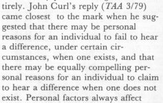
Though I chuckled when they called on Gordon Holt, the man who went on record saying:
"Audio as a hobby is dying, largely by its own hand. As far as the real world is concerned, high-end audio lost its credibility during the 1980s, when it flatly refused to submit to the kind of basic honesty controls (double-blind testing, for example) that had legitimized every other serious scientific endeavor since Pascal. [This refusal] is a source of endless derisive amusement among rational people and of perpetual embarrassment for me".
Another thing that made me smile was the attribution to a statement by you, that there may be personal reasons to hear what's not there, or not to hear what's there. You forgot all about that?
Jan
Attachments
- Status
- Not open for further replies.
- Home
- Member Areas
- The Lounge
- Sound Quality Vs. Measurements