I have read that Cmoy with Opa2134 needs a gain of 10x to be stable.
Is there a way to have a gain of 2x with the Opa2134 using the Cmoy design?
I don't need to amplify too much the voltage gain.
Regards.
Alfredo Mendiola Loyola
Lima, Peru
Is there a way to have a gain of 2x with the Opa2134 using the Cmoy design?
I don't need to amplify too much the voltage gain.
Regards.
Alfredo Mendiola Loyola
Lima, Peru
I have read that Cmoy with Opa2134 needs a gain of 10x to be stable.
Nope - the 134/2134/4134 series are internally compensated and will do just fine even with a gain of 1x (unity gain current buffer).
The biggest potential problem though is whether that chip has enough current drive capability for your specific headphones. What brand / model of headphone are you using the amp with, or alternatively the impedance and sensitivity?
Last edited:
Nope - the 134/2134/4134 series are internally compensated and will do just fine even with a gain of 1x (unity gain current buffer).
The biggest potential problem though is whether that chip has enough current drive capability for your specific headphones. What brand / model of headphone are you using the amp with, or alternatively the impedance and sensitivity?
I'm using a sony 7506 with 64 ohm of impedance.
It works well with 1.5 v rms
I'm using a sony 7506 with 64 ohm of impedance.
It works well with 1.5 v rms
Those have a 106dB/mW sensitivty. For 95dB SPL they would only need around 0.07Vrms and about 1mA(rms) per channel current. So yes, with those, a CMOY would probably work just fine. So would that chip.
Have you built or seen a CMoy using the OPA2134 with a gain of 2 ?
For example rf=1k, rg=1k ?
I will buy a better headphone later with higher impedance.
Regards.
Alfredo Mendiola Loyola
Lima, Pery
For example rf=1k, rg=1k ?
I will buy a better headphone later with higher impedance.
Regards.
Alfredo Mendiola Loyola
Lima, Pery
I haven't built one, but you are right, you will get a gain of 2 with Rf = 1k and Rg = 1k. The CMOY is just a non-inverting op-amp circuit:
Operational amplifier applications - Wikipedia, the free encyclopedia
so the gain equation is gain = [1 + (Rf / Rg)] = (1 + 1k/1k) = 2 in your case.
I see where you are getting that 10x from. Chu Moy's original article on Headwize used 10x (10K/1K):
A Pocket Headphone Amplifier | HeadWize
Tangent's article uses the same ratio:
How to Build the CMoy Pocket Amplifier
and that is just way way too much gain for just about any headphone and source combination. 10x gain isn't required, it is just the numbers Chu happened to pick for his example.
The amount of gain you need depends on the voltage output of your source along with the voltage requirements of your headphone. Some pocket players are all the way down to 0.5Vrms maximum output. A lot of home gear has outputs more in the 2Vrms range. For use with home gear a 1x - 2.5x gain is often enough (1x = just a current buffer if someone has headphones that need more current). For portable players 2x or 4x gain will usually do the job. Ocasionally you may need to go up to 6x or so.
You are lucky that your headphones have both a high(er) impedance and high sensitivity. CMOYs won't work with headphones that have low sensitivity and/or low impedance. The current requirements are too much for many op amps.
Last edited:
I have read that we can reduce the risk of oscillation increasing the gain to reduce the op amp bandwidth.
I want to reduce the BandWidth using a capacitor in parallel with the feedback resistor.
What I don't know is if the Cmoy input Pot (10K) wiper position can affect the low pass filter cut off frequency of the Capacitor in parallel with the feedback resistor.
If I reduce the BandWidth from 8 mhz to 1 Mhz using the Capacitor in parallel with the feedback resistor and then I increase the Gain by 20dB, Will the 1Mhz BandWidh be reduced lower than 1 Mhz?
Regards.
Alfredo Mendiola Loyola
Lima, Peru
I have read that we can reduce the risk of oscillation increasing the gain to reduce the op amp bandwidth.
I want to reduce the BandWidth using a capacitor in parallel with the feedback resistor.
What I don't know is if the Cmoy input Pot (10K) wiper position can affect the low pass filter cut off frequency of the Capacitor in parallel with the feedback resistor.
Rolling off the closed-loop gain to 1 at frequencies above the audio band with the capacitor in parallel with the feedback resistor is a good thing to do. An audio amp really has no business amplifying signals significantly above the audio band. Doing so won't add anything to the audio signal and introduces the chance of amplifying RF or oscillating, as you mention. HOWEVEVER - when you do this it is important to make sure your op amp is "unity gain stable" or "stable at a noise gain of 1", which your OPA2134 is, otherwise high frequencies (or HF noise) can result in a closed loop gain near 1 through the feedback cap and actually cause oscillation.
Also be sure to bypass the chip power pins to ground with 0.1 or 0.01uF caps close to the power pins to prevent oscillation due to inductance in power PC traces and/or wiring.
Since the circuit is set up as a non-inverting op amp the volume control won't have any effect on the capacitor in parallel with the feedback resistor since it attaches to the non-inverting op amp input.
To find the 3dB down point of the circuit use: 1 / [6.28 * Cf * Rf] where Rf is your feedback resistor of course (1K) and Cf is your capacitor in parallel. A 470pF will give a 3dB point of around 330K. You probably don't want your 3dB point to be any closer to 20KHz than 100KHz or so, otherwise the gain would start the decline in the audio band.
The feedback capacitor should be film or COG MLCC ceramic since they affect the audio the least.
BTW, in my math in the previous post I screwed up the gain of the Chu Moy and Tangent circuit. With a Rf of 10K for non-inverting that actually gives you a gain of 11 rather than 10: (1 + 10K/1K). In an inverting op amp circuit you would just get the gain of (minus) 10: -10K/1K.
Last edited:
Rolling off the closed-loop gain to 1 at frequencies above the audio band with the capacitor in parallel with the feedback resistor is a good thing to do. An audio amp really has no business amplifying signals significantly above the audio band. Doing so won't add anything to the audio signal and introduces the chance of amplifying RF or oscillating, as you mention. HOWEVEVER - when you do this it is important to make sure your op amp is "unity gain stable" or "stable at a noise gain of 1", which your OPA2134 is, otherwise high frequencies (or HF noise) can result in a closed loop gain near 1 through the feedback cap and actually cause oscillation.
Also be sure to bypass the chip power pins to ground with 0.1 or 0.01uF caps close to the power pins to prevent oscillation due to inductance in power PC traces and/or wiring.
Since the circuit is set up as a non-inverting op amp the volume control won't have any effect on the capacitor in parallel with the feedback resistor since it attaches to the non-inverting op amp input.
To find the 3dB down point of the circuit use: 1 / [6.28 * Cf * Rf] where Rf is your feedback resistor of course (1K) and Cf is your capacitor in parallel. A 470pF will give a 3dB point of around 330K. You probably don't want your 3dB point to be any closer to 20KHz than 100KHz or so, otherwise the gain would start the decline in the audio band.
The feedback capacitor should be film or COG MLCC ceramic since they affect the audio the least.
BTW, in my math in the previous post I screwed up the gain of the Chu Moy and Tangent circuit. With a Rf of 10K for non-inverting that actually gives you a gain of 11 rather than 10: (1 + 10K/1K). In an inverting op amp circuit you would just get the gain of (minus) 10: -10K/1K.
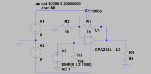
I will use rf=1k and rg=1K, cf=1200pf silver mica.
Is there any problem if I use a power supply with +/- 5volts instead of 9 volts with the cmoy design?
I have read that pcb traces of the op amp inputs must not be placed above a ground plane bottom layer to reduce capacitance, is it true for the cmoy design ?
Thank you for your help.
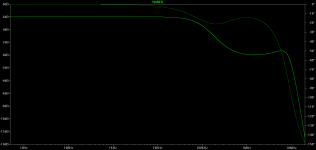
Below are a couple of LT Spice plots with the OPA2134 Spice math model.
The first is the AC plot, showing that with 1200pF the gain starts to drop at 10KHz, but just very slightly. 1200pF should be OK and so is silver mica. If you have a smaller value kicking around though, like 1000pF or 820pF, that would move the start of the gain drop out past 20KHz.
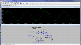
Interestingly enough +/-5Vdc supplies don't seem to make any difference with that chip vs. the +/-9Vdc, at least as far as the Spice model is concerned. The actual non-simulation results will probably be different. 🙂 I would have expected clipping against the power rails to start a few 100mV sooner with the lower +/-5vdc rails. But the Spice plots for both +/-9Vdc and +/-5Vdc Show the start of clipping at 1.3Vpeak (=0.91Vrms), which is half way rotation on a 10K volume pot with the 2Vrms input.
One suggestion would be to put a 10K resistor in series with your input. That will form a 50/50 voltage divider with a 10K pot and drop your 2Vrms input down to 1Vrms. That will insure that you never drive the stage into clipping past 1.2Vpeak (=0.84Vrms).
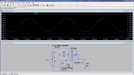
The first plot below is the AC plot with the solid line being the gain and the dotted the phase. Next is the transient plot with +/-5Vdc power supplies and a 1.2Vpeak input, just before clipping. The final plot is +/-5Vdc suppies and 1.3Vpeak, into clipping. The transient plots with +/-9Vdc rails were exactly the same, oddly enough, with 1.3Vpeak still being the onset of clipping.
The reason the amp starts clipping is the current output capability of the op-amp gets exceeded. In the 1.3Vpeak plot I've also plotted the current through the load, which is the blue trace and right-hand scale. You can see that at the 2.5Vpeak (=1.77Vrms) output level (2.5V/1.3Vpk = approx gain of 2 = 6dB) the peak current is 40mA, just all the chip can handle. Even then the chip might be past its power dissipation limits for that DIP8 package. You would have to do some math on that - or just put a finger on it and make sure its not overheating. But with the high sensitivity of your headphones you should not need to crank it up to anything near 0.9Vrms.
Clearing a ground plane "hole" around the op-amp input pins is a good idea. I've done that on a couple of PC boards here. It prevents capacitive coupling from one input pin to the other, and/or from the output pin/trace to input pins, via the ground plane. It probably won't make any difference in a CMOY, but it can't hurt either. It becomes more inportant with very sensitive (nanovolt) inputs and/or high(er) frequencies.
Attachments
Last edited:
Below are a couple of LT Spice plots with the OPA2134 Spice math model.
The first is the AC plot, showing that with 1200pF the gain starts to drop at 10KHz, but just very slightly. 1200pF should be OK and so is silver mica. If you have a smaller value kicking around though, like 1000pF or 820pF, that would move the start of the gain drop out past 20KHz.
Interestingly enough +/-5Vdc supplies don't seem to make any difference with that chip vs. the +/-9Vdc, at least as far as the Spice model is concerned. The actual non-simulation results will probably be different. 🙂 I would have expected clipping against the power rails to start a few 100mV sooner with the lower +/-5vdc rails. But the Spice plots for both +/-9Vdc and +/-5Vdc Show the start of clipping at 1.3Vpeak (=0.91Vrms), which is half way rotation on a 10K volume pot with the 2Vrms input.
One suggestion would be to put a 10K resistor in series with your input. That will form a 50/50 voltage divider with a 10K pot and drop your 2Vrms input down to 1Vrms. That will insure that you never drive the stage into clipping past 1.2Vpeak (=0.84Vrms).
The first plot below is the AC plot with the solid line being the gain and the dotted the phase. Next is the transient plot with +/-5Vdc power supplies and a 1.2Vpeak input, just before clipping. The final plot is +/-5Vdc suppies and 1.3Vpeak, into clipping. The transient plots with +/-9Vdc rails were exactly the same, oddly enough, with 1.3Vpeak still being the onset of clipping.
The reason the amp starts clipping is the current output capability of the op-amp gets exceeded. In the 1.3Vpeak plot I've also plotted the current through the load, which is the blue trace and right-hand scale. You can see that at the 2.5Vpeak (=1.77Vrms) output level (2.5V/1.3Vpk = approx gain of 2 = 6dB) the peak current is 40mA, just all the chip can handle. Even then the chip might be past its power dissipation limits for that DIP8 package. You would have to do some math on that - or just put a finger on it and make sure its not overheating. But with the high sensitivity of your headphones you should not need to crank it up to anything near 0.9Vrms.
Clearing a ground plane "hole" around the op-amp input pins is a good idea. I've done that on a couple of PC boards here. It prevents capacitive coupling from one input pin to the other, and/or from the output pin/trace to input pins, via the ground plane. It probably won't make any difference in a CMOY, but it can't hurt either. It becomes more inportant with very sensitive (nanovolt) inputs and/or high(er) frequencies.
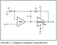
Dear All:
If I want to add a Buf634 in the Opa2134 feedback.
How must I connect ( the Capacitor of 1200pf in parallel with Rf ) with the Buf634 Output?
I have seen schematics where the Feedback capacitor is connected to the opamp output and the Rf to the buf634 output. (But in this case the Capacitor of 1200pf is no in parallel with Rf to the opa2134 output)
Thank you for your help!
Regards.
Alfredo Mendiola Loyola
Lima, Peru
Last edited:
Dear All:
If I want to add a Buf634 in the Opa2134 feedback.
How must I connect ( the Capacitor of 1200pf in parallel with Rf ) with the Buf634 Output?
I have seen schematics where the Feedback capacitor is connected to the opamp output and the Rf to the buf634 output. (But in this case the Capacitor of 1200pf is no in parallel with Rf to the opa2134 output)
Thank you for your help!
Regards.
Alfredo Mendiola Loyola
Lima, Peru
I have found this:
This capacitor (C1), along with R1 and RF, forms a low-pass filter which prevents high-frequency circuit oscillation
I have calculated the cut off frequency just using Rf(1K) the Cf (1200 pf) before include the Buf634 in the Opa2134 feedback.
But now R1 must be included in the cut off frequency.
How do I calculate the cut off frequency using R1, Rf and Cf?
fc= 1/(2*PI*R*C)
I'm analyzing the attached schematic.
Regards
Alfredo Mendiola Loyola
Lima, Peru
Attachments
I did a few calculations using the 106dB/mW and a maximum SPL of 110dB
An output of 565mVpk into 64r is equivalent to 2.5mW
2.5mW produces 4dB more output than 1mW and thus you get 110dB.
If the driver inside the headphones draws a peak transient current that is 1.5times what a 64r resistor would draw at the maximum output then the maximum current demand is ~ 9mApk.
add 0.5mA for the feedback resistor.
add 1mA for parasitic capacitances
The total current demand is likely to be a maximum of 10.5mApk when trying to give 110dB.
A 2134 can easily manage that. A rough guide for low distortion current delivery is half the short circuit current.
You would be well under that.
Last edited:
I'm not sure how high-frequency distortion would look though - the 2134's load immunity up there isn't overly extraordinary.
C1 isn't overly easy to calculate. Its effect depends on R1, Rf and opamp input capacitance (opamp output impedance also plays in). I think it's usually hand-optimized, and values tend to end up in the 22-68 pF range.
C1 isn't overly easy to calculate. Its effect depends on R1, Rf and opamp input capacitance (opamp output impedance also plays in). I think it's usually hand-optimized, and values tend to end up in the 22-68 pF range.
W.Jung has a few articles on composite opamps.
Thnak I have read that book but there in no formula tu calculate the value of C1 of the last schmatic Opa2134-BUF634.
I will have to use my oscilloscope to calculate the cut off frequency.
Regards.
Alfredo Mendiola Loyola
Lima, Peru
Below are a couple of LT Spice plots with the OPA2134 Spice math model.
The first is the AC plot, showing that with 1200pF the gain starts to drop at 10KHz, but just very slightly. 1200pF should be OK and so is silver mica. If you have a smaller value kicking around though, like 1000pF or 820pF, that would move the start of the gain drop out past 20KHz.
Interestingly enough +/-5Vdc supplies don't seem to make any difference with that chip vs. the +/-9Vdc, at least as far as the Spice model is concerned. The actual non-simulation results will probably be different. 🙂 I would have expected clipping against the power rails to start a few 100mV sooner with the lower +/-5vdc rails. But the Spice plots for both +/-9Vdc and +/-5Vdc Show the start of clipping at 1.3Vpeak (=0.91Vrms), which is half way rotation on a 10K volume pot with the 2Vrms input.
One suggestion would be to put a 10K resistor in series with your input. That will form a 50/50 voltage divider with a 10K pot and drop your 2Vrms input down to 1Vrms. That will insure that you never drive the stage into clipping past 1.2Vpeak (=0.84Vrms).
The first plot below is the AC plot with the solid line being the gain and the dotted the phase. Next is the transient plot with +/-5Vdc power supplies and a 1.2Vpeak input, just before clipping. The final plot is +/-5Vdc suppies and 1.3Vpeak, into clipping. The transient plots with +/-9Vdc rails were exactly the same, oddly enough, with 1.3Vpeak still being the onset of clipping.
The reason the amp starts clipping is the current output capability of the op-amp gets exceeded. In the 1.3Vpeak plot I've also plotted the current through the load, which is the blue trace and right-hand scale. You can see that at the 2.5Vpeak (=1.77Vrms) output level (2.5V/1.3Vpk = approx gain of 2 = 6dB) the peak current is 40mA, just all the chip can handle. Even then the chip might be past its power dissipation limits for that DIP8 package. You would have to do some math on that - or just put a finger on it and make sure its not overheating. But with the high sensitivity of your headphones you should not need to crank it up to anything near 0.9Vrms.
Clearing a ground plane "hole" around the op-amp input pins is a good idea. I've done that on a couple of PC boards here. It prevents capacitive coupling from one input pin to the other, and/or from the output pin/trace to input pins, via the ground plane. It probably won't make any difference in a CMOY, but it can't hurt either. It becomes more inportant with very sensitive (nanovolt) inputs and/or high(er) frequencies.
Dear Agdr:
Could you send me by email your spice model please?
Regards.
Alfredo Mendiola Loyola
Lima, Peru
- Status
- Not open for further replies.
- Home
- Amplifiers
- Headphone Systems
- CMoy Opa2134 minimum Gain