Load current depends on load impedance. A 22k pot with 30v between terminals, typical for an amp operating at 18v rails and btl, will draw around 1.3mA. Not an issue even at full output.
A Class D amp needs a dummy load or a speaker for a different reason, and that is filter performance. Since the frequency response of a Class D amp has a very strong correlation with the load impedance, testing without a load will cause an erroneous result.
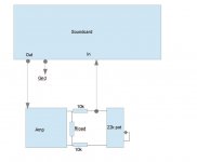
There is a very simple way to wire a pot for btl output amps, two additional resistors are needed and the pot is connected between the outputs with the resistors in series between terminals 1&3, the wiper is connected to either end. One pole is connected to the soundcard input and the ground is common.
A couple of questions:
1- Since the correlation between load and freq response is an important aspect (the speaker beig an integral part of the filter in this specific class D topology) how can someone go about measuring the actual full power or at least half power response into an 8 ohm load without exceeding the soundcard's limits?
2- I would very muh appreciate a drawing of the setup you describe above, I'm having a very hard time visualizing it 🙂
Thanks
Hi
A conceptual drawing is attached. To protect the soundcard, if you feel it necessary, a pair of 3.3V zeners (back-to-back) across the output of this circuit will restrict the input voltage to the card. A string of diodes could also be used, but you will get hard clipping at the threshold. It wold be a bit fiddly to find the threshold, so you would need to use a DMM. But if you have a DMM anyway, you don't need the protection. A simple measurement is enough.
The best way would be to keep the pot at minimum value, which is the wiper turned so that the two resistors are connected to each other. This basically results in net zero voltage into the soundcard. You could feed a 1KHz test tone into the amp and turn it so that REW meters start to move and reach the right level. You could test as high as you wanted, for higher power output you would use less rotation of the pot. At higher levels, you could test the jig's output with a DMM before connecting the soundcard input, or use a small mixer with the feed to the card muted till you are sure of the levels. A level of about 1V should be ideal for most applications. Some balanced input pro cards like the ones I use can directly tolerate the 1W nominal test (2.83V) without any problems whatsoever.
This scheme is often used to trim input levels etc on balanced equipment, which is also fully differential.
As to load and distortion or frequency response, it would be your choice to use fixed resistor, actual speaker or simulated speaker, as per your measurement objectives and materials on hand. The point was that if you use no load, the pot will still not be destroyed upto the current limit of the material used in it.
Attachments
Txs! If you leave your speaker connected as Rload here, do you then measure the amps distortion on your speakerload (plus R's and pot), but without the speakerdistortion?
Pretty much, though the impedance of the speaker and its influence on the amp's response changes rapidly with level. Also with a live speaker, you are going to subject it to a lot of stress if you test too loud. Not to mention your ears.
You would be surprised at how loud a 2khz test tone is when played at 2w, even through a 82dB efficient speaker.
You would be surprised at how loud a 2khz test tone is when played at 2w, even through a 82dB efficient speaker.
This is the circuit I was thinking of when I said a real power resistor load is needed and a voltage divider to drop the voltage across the resistor down to a safe level acceptable to the sound card input. For the typical 19 volt laptop supplies we all use on the 3116, the max voltage is probably no more than 17 or 18 volts. Most soundcards can probably accept 1 volt peak to peak no problem. So a 20:1 voltage divider should be sufficient. That is a good idea to add those 20k series resistors to limit current and then use a 50k pot adjusted at 20:1 position. Then you can crank up the volume as high as you wanted and not worry about blowing the sound card. I have blown a sound card using just the headphone outputs from the sound card through a 150 ohm resistor back into the line inputs of the same soundcard when doing TS measurements of a driver in REW - when I set the output gain to a level that was close to max (-7dB FS). You would think the headphone outputs are not that high but apparently they are. That is why I said be careful if hooking a real power amp up to the sound card inputs.
Thanks for the sketch and the explanation.
I guess one could use the actual speaker as load to tune and tweak the output LC filter, and then revert to high power resistors for a full power distortion analysis?
I guess one could use the actual speaker as load to tune and tweak the output LC filter, and then revert to high power resistors for a full power distortion analysis?
This is the circuit I was thinking of when I said a real power resistor load is needed and a voltage divider to drop the voltage across the resistor down to a safe level acceptable to the sound card input.
A pot is a voltage divider. This special arrangement is needed only because of the balanced output, because without them the outputs would short out at one end of the wiper travel. Correctly wired, a pot would not suffer on its own, and perform its intended function.
Thanks for the sketch and the explanation.
I guess one could use the actual speaker as load to tune and tweak the output LC filter, and then revert to high power resistors for a full power distortion analysis?
Yes, that it one way to do it.
I haven't done much research on this amp, just jumped in the thread to save someone a bit of cash on a mic. I believe the 3116 is a filterless amp for short load runs, so I suppose it can even be tested without the output LPF if the fixed resistor is mounted right on the output. It may not be necessary to actually desolder anything.
Since the LPF and speaker work together to shape the amp's frequency response, it is possible that you may still end up with an anomalous/variable result with either in the circuit. Correlation to real world performance in situations and with products like this will probably not be ideal but then you're not looking for that level of accuracy, I'm guessing.
can I power these three units with one 24v 6A brick 2 3116monoblocks and a 24v preamp


Last edited:

Hello all,
Today I got my yuanjing 2.1 red board. I hooked everything up and works good except the left channel. It is very quiet and distorted. I don't know what is wrong, the hardware looks good. I also tried bypasing the potentiometer but it doesn't help. Can anyone help me? Any ideas?
Thank you
Lukas
Today I got my yuanjing 2.1 red board. I hooked everything up and works good except the left channel. It is very quiet and distorted. I don't know what is wrong, the hardware looks good. I also tried bypasing the potentiometer but it doesn't help. Can anyone help me? Any ideas?
Thank you
Lukas
Hello all,
Today I got my yuanjing 2.1 red board. I hooked everything up and works good except the left channel. It is very quiet and distorted. I don't know what is wrong, the hardware looks good. I also tried bypasing the potentiometer but it doesn't help. Can anyone help me? Any ideas?
Thank you
Lukas
The TPA3116D2 is a very reliable and foolproof chip, most problems, invariably, are caused by poor solder joints, or bad components. So check for the following:
1. solder bridges or cold solder joints on SMT pads of chip (use audible continuity checker probes and make sure pins that are not supposed to be grounded do not beep when checked for continuity with ground)
2. bad input coupling capacitor (make sure it is not shorted or blown)
3. bad bootstrap capacitor (make sure it is not blown)
4. bad opamp pre-amp section (for some 2.1 implementations)
5. check output RLC filter components
On chinese amps Left is the channel also used in PBTL, so on inputside signal is splitting somewhere, any part towards the .1 subamp could also cause problem. If left side PVCC elco is bad it also has strange effect on sound, a friend of mine had 2 bad elco's (jamicon) on blueboard, very strange distorted sound!!!
The TPA3116D2 is a very reliable and foolproof chip, most problems, invariably, are caused by poor solder joints, or bad components. So check for the following:
1. solder bridges or cold solder joints on SMT pads of chip (use audible continuity checker probes and make sure pins that are not supposed to be grounded do not beep when checked for continuity with ground)
2. bad input coupling capacitor (make sure it is not shorted or blown)
3. bad bootstrap capacitor (make sure it is not blown)
4. bad opamp pre-amp section (for some 2.1 implementations)
5. check output RLC filter components
I checked the grounds and they are good, all capacitors are also fine, and output filters also seem fine. I have also tried puting the audio signal direct in front of the input capacitor (bypasing the preamp) and it is the same. Don't know what is causing the trouble 🙁
On chinese amps Left is the channel also used in PBTL, so on inputside signal is splitting somewhere, any part towards the .1 subamp could also cause problem. If left side PVCC elco is bad it also has strange effect on sound, a friend of mine had 2 bad elco's (jamicon) on blueboard, very strange distorted sound!!!
Just tried the elco's and they are good. I also have jamicon.
YJ 2.0 speaker turn-on pop...
Hi,
I have a YJ 2.0 red board (stock, with only changed pot) - and I have the usual turn-on "speaker pop" problem.
I've tried solution from p 172 of this thread (with 100 uF 25V electrolytic cap), but it doesn't help...
Is there a definitive solution to turn-on pop for red 2.0 boards?
johhnygrace had a similar problem, and many others, but the only solution was a cap between ground and 100K resistor tied to SDZ pin - e.g. as in photos in post #2492 by johhnygrace....
Anything else I could try before I start fiddling with relays?
I'm planning to put the TPA3116 into the same enclosure with my Raspberry Pi + Wolfson audio card (24/192 capability, excellent sound) to make an all-in-one audio server + amp (most likely with 20x4 LCD and IR remote), and the only problem left is this annoying (and unpleasant) turn-on speaker pop when I turn on the power...
I know that I can avoid it if I turn down the volume using the pot, but that's not a foolproof solution...
can I power these three units with one 24v 6A brick 2 3116monoblocks and a 24v preamp
An externally hosted image should be here but it was not working when we last tested it.An externally hosted image should be here but it was not working when we last tested it.
a little help please.
So I thought that I bypassed the preamp when I put the input audio signal direct in front of the input cap (1uF), but it turns out that the treble adjustment still works, so that means that the preamp still works? Could anyone show me how to correctly bypass the preamp?
Thank you.
Thank you.
Layout Done and Summary Features:
- TH Parts
- S/D PIN
- MUTE PIN
- SYNC PIN ( For Multi-Boards Linkup e.g 2.1)
- BTL and PBTL Option
- Shielded Inductors [10 x10 mm]
- Board Size: 1.96" x 1.96" / 50 x 50 mm

Ultimate Version 🙂
Below Features:
- More Inductor Footprint Support e.g SAGAMI 7G Series, SMT and Choke power inductors
- ALL TH Parts
- S/D PIN
- MUTE PIN
- SYNC PIN
- LED Power Indicator
- BTL and PBTL Option
- Anti-Pop Speaker Protection
- Two Big ECaps Footprint (Dia. 18.2mm, up to 6800uF/35V for Bass)
- Two Axial Caps Footprint (30x13.5mm, more replacement option
- Board Size: 65mm x 100mm

Replace the Jamicons!!!!So I thought that I bypassed the preamp when I put the input audio signal direct in front of the input cap (1uF), but it turns out that the treble adjustment still works, so that means that the preamp still works? Could anyone show me how to correctly bypass the preamp?
Thank you.
Replace the Jamicons!!!!
But it also does not work with them or without them, so I don't think that they are the problem. Left channel is the trouble, right and sw work good.
- Home
- Amplifiers
- Class D
- TPA3116D2 Amp