When I switch off the PSU or any other equipment that has large caps, it takes a long while before they discharge, and depending on the circuit you can see LEDs flickering, relays resetting after a while etc.
I would like to discharge the caps quickly when power is lost.
*******
Idea 1:
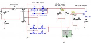
Short the cap permanently through a low resistor (say 10R) and a PNP transistor or a P-Channel MOSFET, which is kept "off" by a positive voltage on its base/gate. I will get this voltage with another bridge rectifier in parallel to the main one. Ideally I would have a separate winding on the transformer so that the voltage at the base of the PNP/FET is slightly higher than the voltage of the main filter cap and keep the transistor well off. When power to the transformer is lost, there will be no voltage at the base of the PNP and it will discharge the cap. I attach a schematic.
Cons: requires extra bridge. Ideally also requires a slightly higher voltage on the gate of the FET to work well, which means another winding.
*******
Idea 2:
Instead of FET use a NC relay - or a 1PDT relay - power through the coil keeps the contacts open. As soon as mains power is off, the coil current will deplete the caps, the relay will close, and will further discharge the cap immediately.
Pros:
Extra fast discharge, just one additional compoment, no bridge required.
Cons:
Continuous relay coil current draw in normal operation.
*****************
I am going for lunch, any suggestions welcome.
I would like to discharge the caps quickly when power is lost.
*******
Idea 1:
Short the cap permanently through a low resistor (say 10R) and a PNP transistor or a P-Channel MOSFET, which is kept "off" by a positive voltage on its base/gate. I will get this voltage with another bridge rectifier in parallel to the main one. Ideally I would have a separate winding on the transformer so that the voltage at the base of the PNP/FET is slightly higher than the voltage of the main filter cap and keep the transistor well off. When power to the transformer is lost, there will be no voltage at the base of the PNP and it will discharge the cap. I attach a schematic.
Cons: requires extra bridge. Ideally also requires a slightly higher voltage on the gate of the FET to work well, which means another winding.
*******
Idea 2:
Instead of FET use a NC relay - or a 1PDT relay - power through the coil keeps the contacts open. As soon as mains power is off, the coil current will deplete the caps, the relay will close, and will further discharge the cap immediately.
Pros:
Extra fast discharge, just one additional compoment, no bridge required.
Cons:
Continuous relay coil current draw in normal operation.
*****************
I am going for lunch, any suggestions welcome.
Attachments
...
*******
Idea 2:
Instead of FET use a NC relay - or a 1PDT relay - power through the coil keeps the contacts open. As soon as mains power is off, the coil current will deplete the caps, the relay will close, and will further discharge the cap immediately.
Pros:
Extra fast discharge, just one additional compoment, no bridge required.
Cons:
Continuous relay coil current draw in normal operation.
*****************
I am going for lunch, any suggestions welcome.
Use line power relay.
This should work for you, and it does not require a separate winding on the transformer..
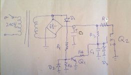
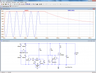
The R3 tries to charge the C1 up to turn on Q2 to discharge the main cap C2, but C1 gets discharged by Q1 through R4 every power cycle so that the gate of Q2 never reaches the turn-on threshold, therefore, Q2 never turns on to do the discharge work until the mains is turned off and Q1 stops discharging C1.
The R3 tries to charge the C1 up to turn on Q2 to discharge the main cap C2, but C1 gets discharged by Q1 through R4 every power cycle so that the gate of Q2 never reaches the turn-on threshold, therefore, Q2 never turns on to do the discharge work until the mains is turned off and Q1 stops discharging C1.
Attachments
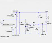
It looks very similar to mine (P-fet vs N-FET)? The separate winding is only needed for perfection but you can use the same winding as the one for the main cap, the loss will be a few mA leaking through the not-fully-closed FET. On simulation at least.
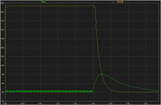
There is a slight difference in how the residue voltage on the main cap goes down at the end of the discharging. In your circuit the Q2 starts to turn off when the main cap voltage drops to the threshold voltage of the MOSFET, and from then on the R2 will finish it off. In my circuit the gate voltage is held by the C1 above threshold (4V in this case) and the MOSFET can completely discharge the main cap. A bleeder resistor is not need.
use a relay that adds a discharging resistor on power OFF.
Light bulbs make a very good PTC style resistor, that varies the resistance to suit the remaining charge voltage in the capacitor/s.
Light bulbs make a very good PTC style resistor, that varies the resistance to suit the remaining charge voltage in the capacitor/s.
Keep it simple just add in a bleeder resistor across any of the caps in the power supply.. google it and understand before solder.
Cheers,
Bob
Cheers,
Bob
"......But not simpler" -- Einstein -- than a breaker in series with that bleeder resistor in this case🙂
"......But not simpler" -- Einstein -- than a breaker in series with that bleeder resistor in this case🙂
I don't get what you mean. The simplest way is a bleeder resistor as mentioned - it's been in practice for many many many years, I expect as long as there's been a capacitor. Just cause you can make it complicated doesn't mean it's a better way, just more things to break down over time. If the bleeder resistor dies it will die open and you won't know it's not working unless you short the cap and in that case you should be using a meter to check for voltage prior to shorting (regardless if there is any bleeder circuitry); that there is SAFETY first.
Cheers,
Bob
It is believed that Einstein once said "........everything should be as simple as it can be but not simpler".
In another words things should not be simpler than would be necessary to serve a purpose.
The topic of this thread is the need and means of quickly and, of course safely, discharging reservoir capacitors at power off. Obviously in order to serve the purpose a low impedance discharging component is required, such as the 10-ohm resistor implied in the opening post, and a breaker is therefore needed in order to disconnect the discharge circuit when not in need.
Your suggestion of using nothing more than a fixed, permanently connected bleeder resistors ( usually of much higher value) certainly is irrelevant to the topic, as these resistors do not serve the intended purpose. So I cannot say it is a better way than one that does serves the intended purpose.
LEDs in CCS in an amp or other part of a system can give a hint when bleeder resistors fail. Even if there are no such readily available indication its not hard at all to make one. A permanently connected bleeder resistor as you suggested can die open too, by the way. So check with a meter before diving in is always a good practice, with or without bleeding circuit, quick one or a slow one.
A properly engineered, complicated system that serves intended purpose always beats one that does not, however simple it can be.
Had simple equaled better in any sense, we perhaps shouldn't have come to diyaudio, as learning and building things make our lives more complicated, or worse, and we can fail our builds from time to time.
Agreed.It is believed that Einstein once said "........everything should be as simple as it can be but not simpler".
In another words things should not be simpler than would be necessary to serve a purpose.
The topic of this thread is the need and means of quickly.....
I will just add that a quick "complicated" discharger is not incompatible with a slow, low-tech one: even with a quick discharger, it is probably a good idea to add a large value bleeder resistor anyway, in series with a high-brightness LED.
For maximum safety, the resistor should be made of two parallel reliable types, and the LED should be shunted by a 4V7 zener, in case it fails open.
Not sold on anything but a bleeder resistor yet.... complicated doesn't = better nor does faster = better.
Elegant + simple = better - I'll stick with bleeder resistor and my trusty DMM. After all just how many times do I really need to worry about caps holding voltage?? Probably 10-15 times while building the device. Takes me a lot less time to test the cap for voltage than it would to build a circuit wire it test it....I don't get the need for some fancy smancy LED whatever to drop voltage on a capacitor. Pretty soon we will be building with a black plastic chassis.😀
Cheers,
Bob
Faster is not better, it is a requirement. Those caps power a number of components and when we switch the unit off, we must either disconnect them from the rest of the circuit or discharge them really quickly (say, less than 1 sec). Both ideas are good, I think disconnecting them is better. We could use an AC relay to take them off the rest of the circuit, that is just one extra component.
akis, whenever there is a 'system' design aspect, you really should start the thread with all relevant requirements, otherwise the forum efforts to help you head off in all directions.
Is there a voltage on the HT DCV that must be below a certain level within a certain time? What is the nominal HT operating voltage, and the capacitance storing the energy that is being discharged? Does the existing main load (eg. output stage with idle current) discharge that capacitance with a certain characteristic already? Is the accessory load (that you are concerned about having voltage on it) a separate load from the main load?
Are you saying you may want to use an AC relay contact to switch HV DC power going to the accessory circuit? Does the accessory circuit have filter capacitance in it, and series resistance?
Last edited:
I am talking about a low voltage AC relay, connected straight to the secondary of the transformer disconnecting everything downwind of the big cap when power is lost.
Maybe I'm getting confused. I thought you were using the relay contact to disconnect circuitry that is being energised by high voltage DC.
Does the 'low voltage AC relay' have a switched contact that is rated to switch high DC volts, or is it just rated for mains AC switching?
Does the 'low voltage AC relay' have a switched contact that is rated to switch high DC volts, or is it just rated for mains AC switching?
Using the secondary of the transformer, in my schematic 24V AC, to power an AC relay which will disconnect the big cap when the AC is lost. Just one extra component.
If we use two extra diodes and an extra capacitor to rectify the same secondary feeding the main cap, we can then use a DC relay.
If we use two extra diodes and an extra capacitor to rectify the same secondary feeding the main cap, we can then use a DC relay.
Ta. The concern I have is not how the relay coil is powered, but the rating of the 'contact' (or terminals) within the relay. That contact will have a specified rating for switching power - with an AC rating, and possibly a DC rating. Unless the relay contact is designed and rated to switch DC current up to a certain voltage, then you may well find the relay contact will fail (high resistance or welded low resistance contact) in a very short time.
- Status
- Not open for further replies.
- Home
- Amplifiers
- Power Supplies
- auto-discharging large caps