Hi there,
My name's Jordan and I'm new here to these forums. I'm 22 and have been into Hi-Fi speakers and equipment for several years now, but have a limited knowledge of electrical circuits and am looking for some guidance on this repair.
I have here an Audionics CC-2 amplifier built in 1978. I first found it (yes, found it) on the side of the road. Amazingly enough it even works. Great find, but the issue is that it has a hum - audible from the amp itself, and emitted through speakers connected to it. The hum is independent (unchanging) with regards to volume level from a preamp. It is also more-or-less equal through both channels. One other possible issue is that the 'clipping indicator' lights on the front are always lit up, though I read on a thread elsewhere that that could be normal. Anyhow, after double checking that it wasn't my other equipment causing the hum, I decided to open it up and see what was going on. I took some photos of the more easily accessible guts (one side of the board). I will add the pictures once I figure out how to do so.
https://imagizer.imageshack.us/v2/1016x677q90/843/1q4fn.jpg
https://imagizer.imageshack.us/v2/1016x677q90/838/6bvw.jpg
https://imagizer.imageshack.us/v2/1016x677q90/834/vnag.jpg
https://imagizer.imageshack.us/v2/1016x677q90/845/xfqk.jpg
https://imagizer.imageshack.us/v2/1016x677q90/834/s33ym.jpg
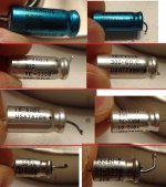
Bulging/blown capacitor visible
https://imagizer.imageshack.us/v2/1016x677q90/835/evj5.jpg
Powered on, with illuminated lights
https://imagizer.imageshack.us/v2/1016x677q90/842/vk1sa.jpg
I know 35 year old capacitors should likely be replaced, but can this be the cause of a hum? Remember the hum is equal in both channels and is not affected by volume level. I discovered a thread with the same issue on another website which I've read through many times. Suggestions such as grounding were brought up, although no solution was ever posted. I can borrow a circuit diagram from that thread if needed.
My name's Jordan and I'm new here to these forums. I'm 22 and have been into Hi-Fi speakers and equipment for several years now, but have a limited knowledge of electrical circuits and am looking for some guidance on this repair.
I have here an Audionics CC-2 amplifier built in 1978. I first found it (yes, found it) on the side of the road. Amazingly enough it even works. Great find, but the issue is that it has a hum - audible from the amp itself, and emitted through speakers connected to it. The hum is independent (unchanging) with regards to volume level from a preamp. It is also more-or-less equal through both channels. One other possible issue is that the 'clipping indicator' lights on the front are always lit up, though I read on a thread elsewhere that that could be normal. Anyhow, after double checking that it wasn't my other equipment causing the hum, I decided to open it up and see what was going on. I took some photos of the more easily accessible guts (one side of the board). I will add the pictures once I figure out how to do so.
https://imagizer.imageshack.us/v2/1016x677q90/843/1q4fn.jpg
https://imagizer.imageshack.us/v2/1016x677q90/838/6bvw.jpg
https://imagizer.imageshack.us/v2/1016x677q90/834/vnag.jpg
https://imagizer.imageshack.us/v2/1016x677q90/845/xfqk.jpg
https://imagizer.imageshack.us/v2/1016x677q90/834/s33ym.jpg
Bulging/blown capacitor visible
https://imagizer.imageshack.us/v2/1016x677q90/835/evj5.jpg
Powered on, with illuminated lights
https://imagizer.imageshack.us/v2/1016x677q90/842/vk1sa.jpg
I know 35 year old capacitors should likely be replaced, but can this be the cause of a hum? Remember the hum is equal in both channels and is not affected by volume level. I discovered a thread with the same issue on another website which I've read through many times. Suggestions such as grounding were brought up, although no solution was ever posted. I can borrow a circuit diagram from that thread if needed.
Last edited:
Hi Jordan and welcome to diyAudio 🙂 Adding a picture is easy, just follow this guide.
To add a photo, files or non standard files.
First click "go advanced" in the box below the "quick reply" message box. Doesn't matter if you decide half way through a message to do that, it carries it forward.
Then click "Manage attachements". Maximise the new Window so that you can see all the text.
Click browse in the first box at the top and find your picture. Repeat for any more pictures.
Click upload... a message appears "uploading"
When complete the files will show as being attached. Now click the small text that says "close this window"
The pictures should now be attached and when you submit your post they will appear.
Make sure your pics aren't too big, a couple of 100k is plenty, and many members object when they are massive and it alters the margins
It tells you in the attachments window what max sizes are allowed.
If you want to attach a file that has a non standard format for example excel, circuit simulation etc then try putting the files in a zipped folder and attaching that.
Thank you for the response. My pictures were enormous, so the forum uploader wouldn't work unless I converted all my photos to a smaller size. I figured I'd just upload them somewhere else and link them here. I hope that's allowed, at least this way it won't distort the dimensions of the forums here 🙂
That capacitor and (based on seeing that one) probably most of the others (the electrolytics) will need replacing. Yes, hum and noise can be one of the most common signs of a failed cap. Ideally a scope would be used to look at any ripple voltage across the cap to give a definite diagnosis.
Thank you for the info Mooly. I just have some questions as I've never done anything like this before. For buying a new capacitor, what would you recommend - simply find one with the same specifications, or is there more to it than that? As in, are some types/brands better for audio applications? Also - is replacing all electrolytic caps on the amp generally a costly thing to do, or cheap?
I may be able to borrow a scope to check on other caps that might not need to be replaced, because generally failed caps don't have to show any visible signs from what I've read. What exactly is ripple voltage?
I may be able to borrow a scope to check on other caps that might not need to be replaced, because generally failed caps don't have to show any visible signs from what I've read. What exactly is ripple voltage?
Ripple voltage is an AC component sitting on top of the DC voltage. If the cap is bad, the ripple is higher and can become audible. So a failed cap might have 40 volts DC across it but also a "ripple" of perhaps 4 or 5 volts of AC.
When looking for caps you need to consider a couple of things. Electrically they need to be of similar or slightly higher value capacitance. Some values that were common years ago have fallen out of use so for example if there were a 560uf (560 microfarad) you could use a 680uf or even a 1000uf. For a 15uf you would use a 22uf. You might find yours are all "modern" values anyway. DC voltage rating. Very important. This must always be equal or higher than the marked value. So if you have 35 volt caps and can't get those then use 63 volt values.
Physical size is another issue. When the wires come out from each end they are called "axial" caps and these too have fallen from favour and are harder to get. When the leads come out of the same end they are "radials" and these are the common ones available today. So make sure that what you buy will fit (or can be made to fit). Modern caps will tend to be much smaller in size than caps of 30 to 40 years ago which can help.
Upgrading the CC2
I saw a post somewhere (Audiogon maybe?) which was about a guy trying to repair his CC2. In that thread, someone posted a list of parts to replace in the CC2 to not only replace old parts, but to improve the design.
Retsel
I saw a post somewhere (Audiogon maybe?) which was about a guy trying to repair his CC2. In that thread, someone posted a list of parts to replace in the CC2 to not only replace old parts, but to improve the design.
Retsel

Power supply caps
I was unable to find that Audiogon thread, but I did find a collection of images on photobucket:Audionics CC-2 Amplifier With Upgrade Photos by daicom | Photobucket.
So I've gotten the two large (power supply?) capacitors out, though after doing that I found the collection of images on photobucket. It looks like this guy wired in 4 extra caps, but left the original ones there. Why would that be?
'Anybody's guess but perhaps the guy imagined it would be better to augment the capacitors rather than just replace the old ones since they are quite expensive and he had smaller values on hand........ It looks like this guy wired in 4 extra caps, but left the original ones there. Why would that be?
Anyways, just because someone makes pics or videos of what they think is an upgrade, doesn't mean they have a clue what they're actually doing.
Actually, on a closer look at the pics showing the electrolytics, I believe those are polypropylene (MKP) or similar film caps which may be 2 -10uF, wired in parallel to the large electrolytics. Some believe this reduces the rising impedance of electrolytic caps at high frequencies and so improves the sound. I take back my comment about strange upgrades since this is widely used, particularly in older equipment with standard grade components.
Last edited:
Large caps
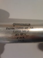
So Here's a photo of the big caps I've gotten out.
Might these be a good choice for replacement ones? Mallory CGS233U040V4C Capacitor 23 000uF 40 VDC | eBay
Seem to be similar size, and slightly larger rating as suggested. I just wonder about how mine say 40 W.V. and these say 50 Volt max surge. Just different lingo, or is there a technical difference?
One other thing, I also found these NEW 15000uF 40V 105C Vishay 058 LOW ESR Capacitor FOR Audio | eBay that have the same specifications as mine... but they're just.... tiny.
Attachments
Electrolytic caps have indeed shrunk dramatically over many years. A peak or surge rating is no longer generally used because of confusion, as you find. Simply ensure that the marked voltage rating is at least 10% higher than the rail voltage your caps are going to have to work at. As your specified rail voltages are +/- 47V, better use the higher standard value of 63V. The 10,000 uF caps specified for the rails are shown as 50V only, which is too close for safety if there are mains variations. So those parts you listed would only be suitable if your amplifier power rails were 35 Volts or less, which isn't the case. If they are being used elsewhere, they are being wasted as the specified values on the schematic will be fine.
One point about Ebay component purchases. How certain are you of getting genuine parts and fresh quality? Caps deteriorate on the shelf without any help from being in an amplifier etc. So the guy sells you a 5+ year old cap and you lose x years service life on the deal. Worth it?
One point about Ebay component purchases. How certain are you of getting genuine parts and fresh quality? Caps deteriorate on the shelf without any help from being in an amplifier etc. So the guy sells you a 5+ year old cap and you lose x years service life on the deal. Worth it?
Thanks very much Ian. I'll definitely try and get fresh parts.
So let me get this straight - are you saying that the small cap I linked would indeed work just the same (Given it were a 63 volt rating of course)? and that the ONLY reason it's smaller is because of advancements in technology?
Also maybe getting caps that resemble the ones I removed from my amp would be a bad idea because that means they are similarly as old?
I think I need to invest in an ESR meter aswell here. What's a good brand/website to get one off and how much should I expect to spend?
Last edited:
Physical size is the main difference for all replacement caps you will be considering. Nothing will simply fit the same as you see when you start looking for equivalents, regardless of the component's alleged quality and the promotional pitch about being designed for audio use...... are you saying that the small cap I linked would indeed work just the same (Given it were a 63 volt rating of course)? and that the ONLY reason it's smaller is because of advancements in technology?
Also maybe getting caps that resemble the ones I removed from my amp would be a bad idea because that means they are similarly as old?
I think I need to invest in an ESR meter aswell here. What's a good brand/website to get one off and how much should I expect to spend?
The most difficult change is that all those smaller electrolytics in your pic. are a style known as axial. That is, their leads run on the circular axis of the part and emerge at each end. This suits the old style electronic designs that were built on tagboard, long ago. There are now very few capacitor types available in this style and it is often cheaper and simpler to bend out the wires of a radial component (leads come out one end, spaced on the same radius).
Make sure there will be room for tall components to fit in the case when mounted this way. Adhere them to the PCB with a small blob or 2 of neutral cure silicone adhesive for stability - don't use hotmelt glue that just melts again with the heat inside. Also, don't just rely on the leads to hold larger parts when spread this way. Secure the cap - you can see what happened to one of the larger caps, possibly caused by lead stress.
Large caps usually have date codes that can be deciphered by downloading the manufacturer's datasheet(s) from the seller or their website. If you can't trust quality before purchase, simply don't buy. Ebay is not the only shopping market in the world, just the first for easy/cheapness that now comes to mind. For electronic components, Digi-Key and others have many more genuine lines and are likely much closer to you.
ESR is a measure for high performance, deep cycling caps but toy ESR meters are seldom any good or any help unless you hope to save on replacing a lot of small old caps. Spend $100 to save $10? The types you see advertised cheap aren't any good for large values and the requirement for big smoothing electrolytics is Ripple Current rating - not simply ESR anyway. Simply put, just replace all old electrolytic caps with good warranted ones with the higher Ripple current ratings from a reputable trade supplier. 10-22,000 uF with >/= 5A ripple current will be fine for the main electrolytics.
Note, you can buy similar shape/size caps to original but compare prices and Ripple current for the same voltage/capacitance ratings - not so attractive: Invalid Request
All Fixed!! Well, nearly..
I just want to say THANK YOU to everyone who has helped me out.
I had my large electrolytics tested at an electronics repair store (he specializes in radios, TVs, and amps, so I figure he knows what he's doing) and one was 'great' and the other had an open circuit. So I bought one 15,000uF and all the smaller ones for the boards, all slightly larger values as recommended. This was originally just to start off with and see where it got me with the buzz issue. After installing the big guy, and all the small er caps on the right channel (the channel with the bulging one in my pics) the buzz is completely gone! I'm so stoked to have fixed it 🙂 I'm still going to get the left channel's caps replaced but as for now I've solved the main issue.
Will post a couple pictures soon.
- Status
- Not open for further replies.
- Home
- Amplifiers
- Solid State
- Audionics CC-2 with a buzz