Getting ready to assemble my build. Its a combo style amp basically using a JTM45 Plexi schematic my opts are 6SL7GT's for the input stages, a 12AT7 long tail PI and a Deluxe power design with 6V6's. I've done an awful lot of research trying to find 6SL7 preamps (Ampeg, Gibson, etc.) on this and I'm sorry to say that in comparing the different circuits I'm still not sure it is correct. The Ra and Rk values are giving me trouble.😕 Can't decide whether to just leave it Ra = 100K / Rk = 820 w/220uf bypass (JTM45 Bluesbreaker w/EC83's) or change it to a more 6SL7 suitable; Ra = 270/ Rk = 2.2k w/100uf bypass (Ampeg M-12)
Any help or opinions will be greatly appreciated.
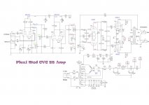
I've attached a copy of my schematic for those interested.
My JTM45 Mod 6V6 BB Amp_B
Any help or opinions will be greatly appreciated.
I've attached a copy of my schematic for those interested.
My JTM45 Mod 6V6 BB Amp_B
Last edited:
Well without looking at the datasheets I believe that the 6SL7 is electrically the same as a 12AX7 except for a lower mu of 70 . The reason for the higher plate load resistors in the M-12 might be for higher gain for it is the only gain stage (and has a mu of 70), the JTM45 has two gain stages.
The JTM45 is the same as the 5F6A bassman except the bassman's circuit was designed for a 12AY7 which has an even lower mu of 45.
The JTM45 is the same as the 5F6A bassman except the bassman's circuit was designed for a 12AY7 which has an even lower mu of 45.
Last edited:
Forgive me. I've paid so much attention to the load values I didn't notice the stage difference.
The 6SL7 is basically the same except for plate load resistance and current.
The 6SL7 is basically the same except for plate load resistance and current.
the 6SL7 is electrically the same as a 12AX7 except for a lower mu of 70.
quite true but i'd run the plates around 250 volt instead of 300 although 300 is its spec rating.
and in my experiance the 6sl7 sounds better i used them in my prolux clone (50 watt 5e3 with 6l6's) , used the standard 5e3 pre but uped the resistors on the plates to lower voltage this is my big harp amp it sounds **** hot, i built another with 12ax7's and wasn't near as impressed. I don't know for sure but i think the biger plates give more bottom end and a fuller sound.
😀
actually i tell a lie pre was not standard was more like this
Attachments
Last edited:
A few 6SL7 preamps for reference.
6SL7 two channel preamp based upon Kevin O'Connors London Power Standard Preamp (LPSP) is posted here:
http://www.diyaudio.com/forums/instruments-amps/251971-power-scaling-2.html
This was a "prototype" amp but it is what I've been using for the last 18 months. Haven't actually felt the need to go back and fine tune it any more. Other guys like it a lot and one guy has requested I build him one identical to it and has come up with the cash.
I also built an amp with the same preamp using 12AX7. I thought the 6SL7 was superior, on the LEAD channel it was easier to set the level of overdrive I wanted and to drive that off the guitar volume control and/or pick attack. The CLEAN channel was possibly slightly low on gain, very clean with just raw guitar (Single Coil PU) but responded well to a using pedals, as in fact, did the lead channel. Also worked well with my Epiphone SG Custom Special with triple humbuckers.
If you search Ampeg Echotwin + Gingertube you should be able to find a schematic trace I did when i restored one of these. It uses 6SL7.
Cheers,
Ian
quite true but i'd run the plates around 250 volt instead of 300 although 300 is its spec rating.
and in my experiance the 6sl7 sounds better i used them in my prolux clone (50 watt 5e3 with 6l6's) , used the standard 5e3 pre but uped the resistors on the plates to lower voltage this is my big harp amp it sounds **** hot, i built another with 12ax7's and wasn't near as impressed. I don't know for sure but i think the biger plates give more bottom end and a fuller sound.
😀
actually i tell a lie pre was not standard was more like this
Thanks for the suggestion. I've modified the load voltages on the schematic. If you can, I'd appreciate if you or gingertube would take a look and give an opinion.
My JTM45 Mod 6V6 BB Amp_B
Again THX for all your help.
Sorry,
I use work internet and I'm blocked from your site. Hoefully ArticBreeze can advise.
Cheers,
Ian
I use work internet and I'm blocked from your site. Hoefully ArticBreeze can advise.
Cheers,
Ian
Why not use 6SL7 for the Phase Inverter too.
That way it is all OCTAL.
For 6SL7 (mu = 70, rp = 44K)
For Anode Load resistors A1/A2 = 1 + {(RL+ra)/Rk(mu+1)}
For 6SL7 A1/A2 = 1 + {82K + 44K)/15K(70+1)}
= 1.118
So want 82K and 82K x 1.118 = 91.7K
Use 82K and 91K
Cheers,
Ian
That way it is all OCTAL.
For 6SL7 (mu = 70, rp = 44K)
For Anode Load resistors A1/A2 = 1 + {(RL+ra)/Rk(mu+1)}
For 6SL7 A1/A2 = 1 + {82K + 44K)/15K(70+1)}
= 1.118
So want 82K and 82K x 1.118 = 91.7K
Use 82K and 91K
Cheers,
Ian
JPG of JTM45 Mod 6V6 BB Amp_B schematic attached.
Hope this helps.
Good luck with your project!
Steve
😕Tried for hours to convert my Turbocad drawing to image. Only way I could fin was to save it as pfd and upload it. How'd you do it.
Really appreciate it apogee.
Was going to use originally 12AT7 then switched to 6SN7 for PI but current transformer is only 700V @90mA (Hammond 273DX)Why not use 6SL7 for the Phase Inverter too.
That way it is all OCTAL.
For 6SL7 (mu = 70, rp = 44K)
For Anode Load resistors A1/A2 = 1 + {(RL+ra)/Rk(mu+1)}
For 6SL7 A1/A2 = 1 + {82K + 44K)/15K(70+1)}
= 1.118
So want 82K and 82K x 1.118 = 91.7K
Use 82K and 91K
Cheers,
Ian
Had to be cheap to save current and don't have room (chassis box is only 17" x 6").
😱Where did you get that formula? Never saw it in any of the sites or books I've got.
Last edited:
The formula is found in most authoritive works on the differential splitter.
The Wiz covers it here:
The Valve Wizard -Long Tail Pair,
If you do the calcs for 12AX7 (mu=100, rp=62K) using 10K tail + 4K7 presence pot (15K total) you end up with the "traditional" 82K + 100K anode loads as giving the best balance. All the "talk" about using 82K and 100K to deliberately unbalance the phase splitter for increased 2nd harmonic distortion and/or better "tone" is just rubbish. Most of the serious designers go for best balance in the PI and some like Howard Dumble include an adjustment to tweek for absolute balance.
Note also that as soon as you start increasing that tail resistance the two required anode resistors rapidly converge. The other "typical" example is 12AX7 with 47K tail which requires anode load resistors so near to equal for best balance, that we just use 100K for both.
I usually take this to extremes when building and choose a twin triode with matched triodes although many will say that that is "over the top".
Cheers,
Ian
Checked my OT (Fender 047269, Blues Deluxe) its winding resistances are off balance (73/82) so I'm going to have to be picky about what goes where.
By the way thanks for the reference went back to the Wizard's papers and found every thing I read a long time ago and forgot.😱
I was thinking more on the input stage anode resistors. Sorry for the confusion but, again THX for all the help.
Tim
By the way thanks for the reference went back to the Wizard's papers and found every thing I read a long time ago and forgot.😱
I was thinking more on the input stage anode resistors. Sorry for the confusion but, again THX for all the help.
Tim
The OT will probably have equal numbers of turns either side of the centre tap, but the resistances are off-balance because one part of the coil is 'on the inside track' and has a shorter length for the same number of turns.
If I am right, this would mean different DC (quiescent) balance to the AC balance. Not sure what we ought to do about this, if anything.
The DC balance prevents the OT from being magnetised (and closer to saturating) under quiescent conditions.
The AC balance gives good output waveform symmetry in the class B region.
I have thought about putting a small resistance in series with the lower resistance side to equalise them, but I've never tried it yet.
The OT will probably have equal numbers of turns either side of the centre tap, but the resistances are off-balance because one part of the coil is 'on the inside track' and has a shorter length for the same number of turns.
If I am right, this would mean different DC (quiescent) balance to the AC balance. Not sure what we ought to do about this, if anything.
The DC balance prevents the OT from being magnetised (and closer to saturating) under quiescent conditions.
The AC balance gives good output waveform symmetry in the class B region.
I have thought about putting a small resistance in series with the lower resistance side to equalise them, but I've never tried it yet.
A couple techs have advised that if one of the output tubes is weaker than the other use the stronger tube on the lower resistance side of OT. This may help balance the output signal.
Hi,
Yes, that makes sense. The stronger tube (the one with a higher quiescent current into a given load for a given bias voltage) should drive the higher resistance side to give a better overall DC balance.
Malcolm
Yes, that makes sense. The stronger tube (the one with a higher quiescent current into a given load for a given bias voltage) should drive the higher resistance side to give a better overall DC balance.
Malcolm
- Status
- Not open for further replies.
- Home
- Live Sound
- Instruments and Amps
- Could use a second opinion.