Measurements of loop gain and the ever popular gain and phase margins are causing confusion for many. I a recent thread, a couple of good posts on this topic emerged. I had a few thoughts myself, so I figured I'd get a new thread started collecting this information.
One way to measure the loop gain is to inject a disturbance signal using a current probe. That is covered well in this article from Maxim: Injection Transformers for Closed-Loop DC-DC Converter Network Analysis - Application Note - Maxim
Current probes generally have rather limited bandwidth, hence, for measurements closer to DC, an op-amp circuit may be more useful. Such a circuit is described in an old app note for the HP 3577A network analyzer: http://cp.literature.agilent.com/litweb/pdf/3577-5131.pdf
Enjoy.
~Tom
Last edited:
Hope all this is more or less on subject.
Maybe something of use about dynamic range-
http://www.diyaudio.com/forums/mult...ed-driver-you-have-worked-15.html#post2840001
And maybe this one-
http://www.diyaudio.com/forums/solid-state/175214-another-view-damping-factor-3.html#post2331997
This is just to help in general.
For open loop gain I simply put a low frequency DC servo on the amp so it will operate without any feedback above 0.01Hz (-3dB on the servo) . It is straight forward from there to measure gain, time delay, frequency response, phase margin, or what ever else is desired.
To test damping factor and impedance of the output, driving the output of the amplifier under test with a different amplifier through various resistors or networks while monitoring signals of the amplifier under test at its' output and the input can be very informative. This is much more informative than loading the amplifier and comparing the no load output voltage to the loaded output voltage to calculate damping factor. A complex model can be created using this method.
More in this thread-
http://www.diyaudio.com/forums/solid-state/161155-solid-state-testing-tug-war.html
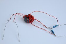
So... I decided to build a Rogowski transformer. I started with a small ferrite toroid that I picked up at a surplus store a while back. I wound 10 turns on it and measured the inductance: 660 uH for 10 turns.
A 15:5 transformer on this core had a usable bandwidth of about 13 MHz. That's not quite enough for the loop gain measurements I'd like to do. So I turned it into a Rogowski transformer by splitting the 50 Ω termination into two 22 Ω resistors (the closest to 25 Ω I had available). With two 15-turn primaries connected in series with 22 Ω*across each primary and the same 5-turn secondary, the bandwidth is now 70+ MHz. I was pretty blown back that I could push 70 MHz through this Daddy Longleg...
~Tom
Attachments
For open loop gain I simply put a low frequency DC servo on the amp so it will operate without any feedback above 0.01Hz (-3dB on the servo) . It is straight forward from there to measure gain, time delay, frequency response, phase margin, or what ever else is desired.
Now, that's cool. I hadn't thought of using a DC servo. One has to be careful with the input signal amplitude, though.
Ironically, that's the exact same method I use in simulation, though, rather than a DC servo, I use a monster LC filter to reject everything except DC. I typically use 1 MH, 1 MF in simulation. That's capital M for mega (1E6) not lower case m for milli (1E-3).
~Tom
So... I decided to build a Rogowski transformer. I started with a small ferrite toroid that I picked up at a surplus store a while back. I wound 10 turns on it and measured the inductance: 660 uH for 10 turns.
A 15:5 transformer on this core had a usable bandwidth of about 13 MHz. That's not quite enough for the loop gain measurements I'd like to do. So I turned it into a Rogowski transformer by splitting the 50 Ω termination into two 22 Ω resistors (the closest to 25 Ω I had available). With two 15-turn primaries connected in series with 22 Ω*across each primary and the same 5-turn secondary, the bandwidth is now 70+ MHz. I was pretty blown back that I could push 70 MHz through this Daddy Longleg...
~Tom
Cool! You are quick.
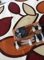
My one is entirely based on the Maxim AN as shown in the picture.
Attachments
Last edited:
Often, you can't break the feedback loop to neatly measure phase and gain. Omicron labs describes a method for non-invasive loop measurement by examining Zout and phase angle -- most of the PDF is used to describe how their current injectors and Bode-100 analyzer are to be used, but the method is easily adapted to the equipment we have at hand:
http://www.omicron-lab.com/fileadmi...notes/App_Note_Noninvasive_Stability_V1_0.pdf
Condensed version here, but annoyingly you have to watch the pop-up:
Evaluate Feedback Stability | Electronic Design | Test & Measurement content from Electronic Design
J
http://www.omicron-lab.com/fileadmi...notes/App_Note_Noninvasive_Stability_V1_0.pdf
Condensed version here, but annoyingly you have to watch the pop-up:
Evaluate Feedback Stability | Electronic Design | Test & Measurement content from Electronic Design
J
Often, you can't break the feedback loop to neatly measure phase and gain. CLIP
J
That being the case, the amplifier is unconditionally unstable because with a bad load and assuming voltage feedback the delay of the feedback signal caused by the bad load will "break" the loop. I do recognize certain designs work well with known loads which require feedback to function. This is not a good choice for audio because the load is indeterminate.
Here is another article describing signal injection using transformer. Ridley Engineering | - AP300 Loop Injection
I will post some data later.
I will post some data later.
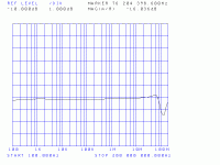
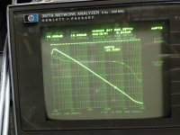
LM3886 loop-gain measurement
The LM3886 shown below is configured as non-inverting amplifier with 1k and 33k as gain setting (feedback) resistors. Loop gain is measured by HP3577A with signal injection method outlined in the Maxim app note.
The signal injection probe has a useable bandwidth from approx. 200 Hz to 10 MHz. Hence, HP3577A frequency range is set to 100 Hz to 10 MHz. From the figure of measured response, we can see roll off around 100 Hz and "noisy" curve due to very high gain. This is not a problem for amplifier loop analysis where high-frequency roll off characteristic is our major concern.
The 0 dB point is where open-loop and closed-loop gain intersect. It can be seen the frequency and phase of this point are 347 kHz and 87.5 (~90) deg, respectively. Phase margin of this particular circuit is thus 90 deg.
Attachments

Last edited:
Nice!
Can I use my 50MHz TEK current probe for this?
Anyone ever use lissajous plot method for this? Have many times in the past.
Would really like to put my 3886 amp in this test just to see. Its gain is really high, 240dB at DC, so there is huge loop gain.
Can I use my 50MHz TEK current probe for this?
Anyone ever use lissajous plot method for this? Have many times in the past.
Would really like to put my 3886 amp in this test just to see. Its gain is really high, 240dB at DC, so there is huge loop gain.
Nice!
Can I use my 50MHz TEK current probe for this?
Anyone ever use lissajous plot method for this? Have many times in the past.
Would really like to put my 3886 amp in this test just to see. Its gain is really high, 240dB at DC, so there is huge loop gain.
Use the current probe to pick signal or inject signal?
3886 DC gain won't be 240 dB. Please check the data sheet.
Another good article for loop measurement http://www.testunlimited.com/pdf/an/5989-8036EN.pdf
Can I use my 50MHz TEK current probe for this?
Using a current probe as a current transformer / injection transformer is often possible. I used a TEK CT-6 current probe for a loop gain measurement. It worked pretty well, though, its primary inductance is too low for measurements much below 200 kHz. For PM/GM at 1 MHz, it worked just fine, though.
~Tom
In case a network analyzer is not available. We can still perform loop analysis with a signal generator and a scope. This is described in this report http://www.ti.com/lit/an/snva364a/snva364a.pdf. Important data such as 0 dB crossover frequency and phase margin can be obtained with basic lab equipment.
A gain/phase meter such as the HP 3575A can be had for not that much money... Add the HP 3312A signal generator and you're set.
Oscilloscopes are not very precise instruments. Following the TI paper would certainly give you a good idea of whether the PM is close to zero, but I wouldn't expect to be able to tell, say, 60º from 70º.
~Tom
Oscilloscopes are not very precise instruments. Following the TI paper would certainly give you a good idea of whether the PM is close to zero, but I wouldn't expect to be able to tell, say, 60º from 70º.
~Tom
In the 1980's Audio Amateur showed a simple phase meter built with a couple opamps and a comparator. Intersil also had a very nice phase meter built with some current feedback amplifiers and a very high speed comparator based upon one of their transistor matrices (HFA3102), I built it, but had to use TI cfb amps which were on hand.
The idea is that the signals are boosted and clamped by the diodes. The RMS signal at the comparator output is proportional to phase. You can make life easy for yourself and use a true RMS detector from Linear Tech or Analog Devices.
I sold my HP 3575A Phase Gain meter and actually made a little money on the deal! The device in typical fashion, gilt the lilly.
An externally hosted image should be here but it was not working when we last tested it.
The idea is that the signals are boosted and clamped by the diodes. The RMS signal at the comparator output is proportional to phase. You can make life easy for yourself and use a true RMS detector from Linear Tech or Analog Devices.
I sold my HP 3575A Phase Gain meter and actually made a little money on the deal! The device in typical fashion, gilt the lilly.
Use the current probe to pick signal or inject signal?
3886 DC gain won't be 240 dB. Please check the data sheet.
CLIP
Sorry to be not clear. It is not a 3886 amp. It is my circuit which uses a 3886 as a power device. DC gain of the complete circuit is 240dB.
In the 1980's Audio Amateur showed a simple phase meter built with a couple opamps and a comparator.
The idea is that the signals are boosted and clamped by the diodes. The RMS signal at the comparator output is proportional to phase. You can make life easy for yourself and use a true RMS detector from Linear Tech or Analog Devices.
The output of that circuit should be a square wave with the duty cycle proportional to the phase angle. In that case, the RMS voltage would be A*sqrt(D), where A is the amplitude and D is the duty cycle of the square wave. The square root is not a linear function...
The average value of the square wave, on the other hand is simply A*D, hence, linear. So I think all you need on the output of that circuit is an RC filter. Or you can get fancy with a Sallen-Key filter to suppress the original frequency a bit more.
~Tom
The output of that circuit should be a square wave with the duty cycle proportional to the phase angle.
~Tom
Yes, there was an "integrator" on the output -- here's the Intersil article:
http://www.intersil.com/content/dam/Intersil/documents/an96/an9637.pdf
- Status
- Not open for further replies.
- Home
- Design & Build
- Equipment & Tools
- Loop gain measurement apparati