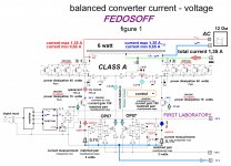
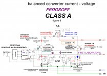
Dear Colleagues. In this branch propose to discuss several current converter circuits - voltage. Description to Figure 1. Currently, digital media is a major source of information practically . There are new digital formats with high resolution. Moreover the process of recording , mixing, mastering , takes place in the digital environment. And the concept of analog amplification was laid decades ago and has not changed . Correctors , equalizer , preamplifiers , power amplifiers , do not forget operational amplifiers directly to CD or DVD device. That is a common analog amplification path consists of many electronic parts - resistors, transistors, capacitors , transformers, respectively, included in series. In addition, proofreaders , equalizer , preamplifiers , power amplifiers connected in series interblock connectors. This so-called - the method of successive amplification of sound signals , clearly exhausted itself , as each electronic component is a loss of particles information. In general, a result significantly affected micro dynamics and overtones. Obviously, it was time to change the ideology of building all the amplification path . To do this, proposed to abandon the usual sequential method of amplifying audio signals and integrate directly into the DAC chip power amp . This will significantly reduce the length of the sound of the analog section , and all the signal correction carried out directly in a digital device . We propose a new method - a powerful converter current - current - voltage , which will amplifier. Method name ITUTS - controlled current source digit. Advantage of the method as soon tract. Implementation of a powerful converter current - current - voltage possible on the basis of any current output DAC . The inverter circuit used RSM1794A , or the like. DAC chip RSM1794A directly integrated into the amplifier. RSM1794A chip , with current output , activated by a standard scheme . In digital mode, zero current is flowing out of 6.5 mA RSM1794A Variable (sound ), the current flowing from RSM1794A is + - 2.5 mA at 0 dB. Proceeding from these values we calculate our powerful converter - amplifier. Principle of operation ITUTS - current source managed following figure . At the base input of the transistor T1 and T2 served differential current flowing directly from the DAC chip RSM1794A . Variable (sound ), the current flowing from the chip RSM1794A ( + - 2.5 mA at 0 dB) is fed directly to the base of transistor 2SA5200 , and the amplified AC occurring at the collector of transistor T1 through T3 composite transistors , 4,5,6,7 misses the primary winding of the transformer sound . Composite transistors T3, 4,5,6,79 (Cascade Shiklai ) enabled by the common base that eliminates the Miller effect in cascode and increases its linearity and frequency. Cascade converter works respectively in Class A. For our converter - amplifier select a matched pair of transistors. Let their current gain is equal to 150. Accordingly 6.5 mA x 150 = 0,750 mA. This is our quiescent current with no signal . Setting mode is as follows. Take out the fuse F1, turn on the device , the engine trimmer P1. Set the voltage of 0,075 volts. For other current gain , respectively exhibit and the reference voltage . The main criterion precisely matched pair . Naturally accurately pick transistors fail. However, in this case we will current balancing scheme which operates as follows. Suppose that initially , the current gain of transistor T1 will be somewhat larger. At the moment of the measuring resistance R6 voltage exceeds the reference appears . This voltage is applied to the non-inverting input of the operational amplifier . At the output of the operational amplifier voltage increases, the emitter of the transistor T13 will also increase , consequently , injury of the same collector current of the transistor , and the voltage across the resistor R23 decrease. This voltage across the resistor R21 and R8, ( representing the filter ) is applied to the gate of the FET IRF240. Correspondingly reduced collector voltage of the transistor T1 . Transistor current decline somewhat . Thus, the circuit returns to the equilibrium state , stabilize the balance of quiescent current . Transistors T1 and T2 are installed together on your individual radiator . It is necessary to take into account the smaller device heats , the accurate and reliable , it works . This applies particularly to the transistors T1 and T2 . Next. Balanced current sent to the audio transformer currents and summation process is carried out directly in the dynamics . Winding of the transformer and speaker at the same time , fulfill the function of the digital filter. When the balance of currents , as usual, the second harmonic is suppressed , and very successfully by the precise balance of the quiescent currents . Thus, the converter current - current voltage serves as the speaker. The primary winding of the transformer prevents DC voltage across the loudspeaker terminals in idle mode . With this concept gain eliminates unnecessary weight gain stages , feedback loops , as well as the most difficult stage is implemented - analog phase inverter. When assembling the converter - current - voltage , it is necessary to take into account that the accuracy of maintaining balanced currents measuring resistors R6 and R1 determines equality resistances. Therefore, it is necessary to pick up a couple of the usual two watt resistors. With this ideology construction amplification path excludes operational amplifiers directly to CD or DVD device , however , everything else is the same . Adjust the volume level is carried out directly from the remote DVD or CD device. The digital part in this article it is not considered the most common - standard . To significantly improve the sound quality offered digital part adaption of individual battery. Powerful balanced converter current - current - voltage , aka power , is a very promising device. For example, a primary winding of the transformer can be connected to high-resistance load - isostatic speaker system This eliminates a huge number of cascades and chains OS. It is necessary that the upper transistors IGBT transistors to replace , insert their common gate , recalculate the upper part of the circuit , the transformer required to submit a positive bias voltage , the lower part will be the common wire , recalculate the load resistance . An output voltage converter balanced current - current - voltage is set automatically depending on the load impedance . For example, when the load on the AC will create a total of 100 ohms an output voltage of 200 volts. In all these cases we have the shortest path and thus the maximum correct ( reliable ) sound. Advantage of the method as soon tract, authentic sound. Lack of OS. Lack of output transformer exaction transistor pairs and measuring resistors . High output impedance . However, in some cases it requires a high output impedance . When assembling the unit yourself , appropriate knowledge. Adjusting the volume on the digital SPDIF. Description for Figure 2 Principle of operation ITUTS - current source managed following figure . DAC chip RSM1794A directly integrated into the amplifier. DAC chip RSM1794A included in mono mode , for greater impact power. In digital mode, zero current is flowing out of 6.5 mA RSM1794A At the base of the transistor T1 is a component directly from the chip DAC RSM1794A served arising variable (sound) current ( + - 5 mA at 0 dB). T1, T2 - transistors connected in parallel . Multiple current generator is automatically configured to sink current of 2 A. When the influent and effluent equality of the inverter output current set to zero potential. For the balance of currents applied to the current controlled oscillator composite transistors T3, T4 , T5 . Stabilizes and defines its base current generator transistor T3. Assume that the inverter output have positive potential, which will be submitted to the inverting input of the operational amplifier. Emitter voltage of the transistor T6 is reduced , it will also decrease the current. Falling on the reference resistor R2 decreases. Correspondingly reduced current upper scheme of the current generator . The scheme will return to the state of the current balance and the output set to 0 volts. Voltage converter current in this circuit is the resistance dynamics . Inductance of the speaker in this case and suppresses digital noise . Dignity circuit simplicity, the shortest path and the right , respectively ( reliable ) sound. Lack of OS. Lack of high output impedance . Adjusting the volume on the digital SPDIF. Description for Figure 3 Principle of operation ITUTS - current source managed following figure . DAC chip RSM1794A directly integrated into the amplifier. In digital mode, zero current is flowing out of 6.5 mA RSM1794A At the base of the transistor T1 is a component directly from the chip DAC RSM1794A served arising variable (sound) current ( + - 5 mA at 0 dB). Part of the current from the emitter to the base T1podaetsya parallel transistors T2. Multiple current generator configured to source current 5 A. When the influent and effluent equality of the inverter output current set to zero potential. For the balance of currents applied current generator on composite transistors T3, T4 , T5 . Stabilizes and defines its basic current controlled oscillator transistor T3. Assume that the inverter output have positive potential, which will be submitted to the inverting input of the operational amplifier. Emitter voltage of the transistor T6 is reduced , it will also decrease the current. Falling on the reference resistor R2 decreases. Correspondingly reduced current upper scheme of the current generator . The scheme will return to the state of the current balance . To increase the impact AC load is applied complementary circuit consisting of a resistor R10. Voltage converter current in this circuit is the resistance dynamics . Inductance of the speaker in this case and suppresses digital noise . Dignity circuit simplicity, the shortest path and the right , respectively ( reliable ) sound. Lack of OS. Lack of high output impedance . Adjusting the volume on the digital SPDIF.
Attachments
Dude, you owe me some new eyes! 😱 Put some paragraph breaks in there!
Oh, ... and nice work and sharp schematics. 🙂
Oh, ... and nice work and sharp schematics. 🙂
Again?
http://www.diyaudio.com/forums/digital-line-level/255301-hybrid-dac-pcm1794-galvanic-coupling.html
so DAC
such natural
reduced current, WOW!
http://www.diyaudio.com/forums/digital-line-level/255301-hybrid-dac-pcm1794-galvanic-coupling.html
so DAC
such natural
reduced current, WOW!
By the way, you can copy the application freely, without any patent infringement, as long as you are out of the following countries list, and do not plan to rule a business there:
Armenia
Azerbaijan
Belarus
Georgia
Kazakhstan
Kyrgyzstan
Russia
Tajikistan
Turkmenistan
Ukraine
as these are the only counties who know of eurasian patents.
FEDOSOFF, Thanks for your free designs!
Armenia
Azerbaijan
Belarus
Georgia
Kazakhstan
Kyrgyzstan
Russia
Tajikistan
Turkmenistan
Ukraine
as these are the only counties who know of eurasian patents.
FEDOSOFF, Thanks for your free designs!
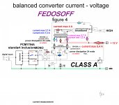
Dear Colleagues, you can build it for home use and for research. Description for Figure 4 IC DAC RSM1794A directly integrated into the amplifier and switched to mono , for greater impact power. In digital mode, zero current is flowing from RSM1794A is 13 mA on a basic input of the transistor T1, T2 directly from the DAC chip RSM1794A . served arising variable (sound) current ( + - 5 mA at 0 dB). Balanced current sent to the audio transformer currents and summation process is carried out directly in the dynamics . Winding of the transformer and speaker at the same time , fulfill the function of the digital filter. When the balance of currents , as usual, the second harmonic is suppressed , and very successfully by the precise balance of the quiescent currents . Thus, the converter current - current voltage serves as the speaker. The primary winding of the transformer prevents DC voltage across the loudspeaker terminals in idle mode . With this concept gain eliminates unnecessary weight gain stages , feedback loops , as well as the most difficult stage is implemented - analog phase inverter. Possible inclusion in the scheme of additional balancing trimmer P2. For better sound quality used two output transformers . Bass and treble . Dignity of the shortest path scheme and accordingly correct ( reliable ) sound. Lack of OS. Lack of output transformer exaction transistor pairs . High output impedance . Adjusting the volume on the digital SPDIF.
Attachments
Description for Figure 5 IC DAC RSM1794A directly integrated into the amplifier and switched to mono , for greater impact power. In digital mode, zero current is flowing from RSM1794A is 13 mA on a basic input of the transistor T1, T2 directly from the DAC chip RSM1794A . served arising variable (sound) current ( + - 5 mA at 0 dB). Balanced currents are sent to a speaker with two windings. Therefore , the process takes place directly summing currents in the winding. Winding dynamics simultaneously perform the function of the digital filter. When the balance of currents , as usual, the second harmonic is suppressed , and very successfully by the precise balance of the quiescent currents . Fine-balancing provided by the tracking system on operational amplifiers . Basic inputs of the transistors act as current adders . As in all previous cases, the converter current - current voltage serves as the speaker. Accurate balancing quiescent current prevents dc voltage across the loudspeaker terminals in idle mode . With this concept gain eliminates unnecessary weight gain stages , feedback loops , as well as the most difficult stage is implemented - analog phase inverter. Possible inclusion in the scheme of additional balancing trimmer P2. Dignity of the shortest path scheme and accordingly correct ( reliable ) sound. Lack of OS. Lack exaction transistor pairs . High output impedance . Adjusting the volume on the digital SPDIF.
Attachments
Hi,
I have 4 eyes already and after my eye surgery I couldn´t follow the text for more than a single line.
On the first picture two issues came up.
- The PCM1794A is a current sourcing DAC with its output swinging by +-3.9mA around a centre of -6.2mA. I see no provision for a DC-current path for this idle current.
- The PCMs outputs feed directly into the two bases of the 2SA5200, whose Emitters idle at +75mV. Hence the bases will be at around -600mV, a value where the internal protection diodes of the PCM will conduct and distort the signal.
- the current outputs of the DAC feed into highohmic bases instead of a very low impedance node. I´d rather expected to see a common base structure at the output of the PCMs. A topology that suits the PCMs and also quite easily allows to design a ´power DAC´
jauu
Calvin
Hello colleague. From practice. When calculating the modes should proceed from the following. RSM1794A - mono. 1 Volt AC voltage 215-ohms. Sound can be heard on the video. For current sources PCM1794A requires a low output impedance. When the effluent stream 13mA input impedance emitter will be about 2 ohms.Hi,
I have 4 eyes already and after my eye surgery I couldn´t follow the text for more than a single line.
On the first picture two issues came up.
- The PCM1794A is a current sourcing DAC with its output swinging by +-3.9mA around a centre of -6.2mA. I see no provision for a DC-current path for this idle current.
- The PCMs outputs feed directly into the two bases of the 2SA5200, whose Emitters idle at +75mV. Hence the bases will be at around -600mV, a value where the internal protection diodes of the PCM will conduct and distort the signal.
- the current outputs of the DAC feed into highohmic bases instead of a very low impedance node. I´d rather expected to see a common base structure at the output of the PCMs. A topology that suits the PCMs and also quite easily allows to design a ´power DAC´
jauu
Calvin
Last edited:
- Status
- Not open for further replies.
- Home
- Source & Line
- Digital Line Level
- News. Powerful current sources controlled PCM1794A.