I need a PCB-layoot an button for the audio amplifier given to schematic.
thank you!
thank you!
Attachments

Last edited:
?
May I ask a question? 🙂
The schematic will work in principle, however it has got some flaws, related to DC offset, stability/compensation, bias trimming, as well as some strange values (non-standard input resistance, non-standard voltage gain = 10, etc.).
The question is - why do you want to build this particular design? 😕
Is it some "homework"? Did you design it yourself? Or it is introduced by somebody? Do you need some recommendations? Or you would rather say "Shut up, just make a PCB for me"? 🙂
Designing a PCB will take 15-20 minutes, but I will better leave it to Mihkus. Just don't want to crash the market 😀
Though I could help with some improvements, making it a practically usable circuit...
BR,
Valery
I need a PCB-layoot an button for the audio amplifier given to schematic.
thank you!
May I ask a question? 🙂
The schematic will work in principle, however it has got some flaws, related to DC offset, stability/compensation, bias trimming, as well as some strange values (non-standard input resistance, non-standard voltage gain = 10, etc.).
The question is - why do you want to build this particular design? 😕
Is it some "homework"? Did you design it yourself? Or it is introduced by somebody? Do you need some recommendations? Or you would rather say "Shut up, just make a PCB for me"? 🙂
Designing a PCB will take 15-20 minutes, but I will better leave it to Mihkus. Just don't want to crash the market 😀
Though I could help with some improvements, making it a practically usable circuit...
BR,
Valery
In advance many thanks to Alex (Pop Alexandru)!.....🙄 I will do it for free for diy members

cheers!

Last edited:
May I ask a question? 🙂
Though I could help with some improvements, making it a practically usable circuit...
Hi Valery!
This interesting schematic-circuit I found on the internet.
Just you go ahead about improving schematic,... I will be much grateful!
best regards!
Last edited:
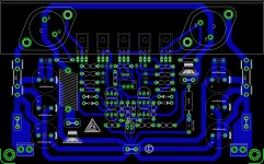

..... first try , not ready but almost done 😉
Alex, very nicely arranged PCB!
If you can PCBs botton in the pdf of the output transistor pair BD249C/BD250C
thank you!
Just some notification:
- I would use 0.22 - 0.33ohm emitter resistors in the output stage to avoid thermal runaway
- I would change the Vbe multiplier, because this version is very dangerous
Sajti
- I would use 0.22 - 0.33ohm emitter resistors in the output stage to avoid thermal runaway
- I would change the Vbe multiplier, because this version is very dangerous
Sajti
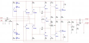
OK, here is the schematic - I tried to keep the changes at minimum.
Input impedance is roughly set to 47k, input filter is added. R13-C4, R14-C3 (original schematic) are removed - they slow down VAS too much, which is compensated enough with C1, C2 (lower values to preserve the bandwidth and keep THD at the higher end low enough). Vbe trimmer - is more secure to keep it between the base and emitter - if it loses the contact, the quiescent current will drop (and save your output transistors). Zobel network - more efficient with RL in place. Global NFB is corrected for 29db standard gain, compensation and DC decoupling.
Working design, but nothing special. I would actually recommend to build some well-designed and tested amp - something developed by ostripper, apexaudio, VSSA versions, etc - there is a bunch of them here.
However, if you like to experiment with the schematic of your choice - go ahead, also a good thing to do 🙂 Keep us posted 😉
Cheers,
Valery
Attachments
Just some notification:
- I would use 0.22 - 0.33ohm emitter resistors in the output stage to avoid thermal runaway
- I would change the Vbe multiplier, because this version is very dangerous
Sajti
Display your idea on the schematic.
thank you!
Valery, recommend a better audio amplifier of your choice who will be power supply with UCC = + / -(35....40)V.
thank you and cheers!
thank you and cheers!
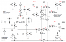
This one would be a good option for you. Well-documented, proven design with PCB layout, BOM, building instructions, etc.:
Greg's DX amplifier
Greg's DX amplifier
This one would be a good option for you. Well-documented, proven design with PCB layout, BOM, building instructions, etc.:
Greg's DX amplifier
So, this amplifier you recommend,...
😉😕
Instead 2sc2500/2sa1943 Is mistaken with tip35c/tip36c?
thanks
Attachments
Last edited:
I would not recommend such substitution - TIP35/36 are at least much "slower" and lower hfe
But you can ask Greg directly - "destroyer X" here
But you can ask Greg directly - "destroyer X" here
PCB for audio amplifier
Respectfully!
Please Alex mm, if you're able to get over on my PCB (PCB-botton Layot in pdf) to the amplifier by the schematic (http://www.siamtech.ac.th/Learning/DreamCourse/dream002/pastana/gun.html) and up to post on my e-mail, you'll be very grateful.
thank you
Best Regards!
Respectfully!
Please Alex mm, if you're able to get over on my PCB (PCB-botton Layot in pdf) to the amplifier by the schematic (http://www.siamtech.ac.th/Learning/DreamCourse/dream002/pastana/gun.html) and up to post on my e-mail, you'll be very grateful.
thank you
Best Regards!
Last edited:
- Status
- Not open for further replies.
- Home
- Amplifiers
- Solid State
- PCB for audio ammplifier with mj15003/mj15004