Hi,
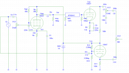
I recently built my own standalone reverb unit for guitar (inspired by the fender 6G15). Since I had a couple 6au6 pentodes lying around I decided to build my driver circuit around one in attempt to make a constant current driver into a 1475 ohm high impedance reverb tank (I got the idea here). The recovery half of the circuit uses a 12ax7 and is directly copied from the 6g15 schematic. Anyway my circuit sounds great for what it is but has some serious issues, specifically that the reverb is a little subtle, and tends to drop out with frequency (a high E has much more reverb than a low E which has barely any). I'm thinking there's an impedance issue somewhere, or its just not producing enough power. Does anyone notice any reason for this based on my attached schematic or have any other tips on improving my circuit?
Edit: Just figured that I should specify that the drive pot in the schematic is 1Meg.
Attachments
Last edited:
Oh yeah sorry I'ts not shown on the schematic but the suppressor grid is directly connected to the cathode.Is the supressor tied to the cathode?
Pgram,
What is the voltage across Rk, the cathode resistor. This should give you an indication where your tube is running at. According to the article, the tube should be running at a few milliamperes to achieve constant current mode.
What is the voltage across Rk, the cathode resistor. This should give you an indication where your tube is running at. According to the article, the tube should be running at a few milliamperes to achieve constant current mode.
Pgram,
What is the voltage across Rk, the cathode resistor. This should give you an indication where your tube is running at. According to the article, the tube should be running at a few milliamperes to achieve constant current mode.
The voltage across is approximately 1.97V according to actual measurements and about 2.2V according to SPICE simulations. As for the suggestion about changing the value of C5 I swapped it out after reading the post with a 0.1u capacitor that I had on hand and the difference is very subtle, which would indicate that the bulk of the problem lies elsewhere.
Thanks all for the input so far!
So it seems that it is running at roughly 6 milliamps. Should be enough. The value of 1475 ohms on the tank, is that at 1 kHz?
Could the problem be on the recovery side?
While I'ts certainly possible, I would seriously doubt it since the recovery half is a tried and true design from fender, the 6g15. Also it makes a pretty big sound if I kick the tank. Anyways here's the 6g15 schematic:
An externally hosted image should be here but it was not working when we last tested it.
here is a copy of my entire schematic (including recovery)

I was thinking though that the problem might be that the two halves of the circuit are loading the guitar signal too heavily and I might benefit by putting some kind of buffer in front of the 6au6, although I want to really avoid using another active stage as this will increase complexity and crowd my enclosure. Might this theory hold any water?
And yes 1475 ohm is at 1kHz
Last edited:
While I'ts certainly possible, I would seriously doubt it since the recovery half is a tried and true design from fender, the 6g15. Also it makes a pretty big sound if I kick the tank. Anyways here's the 6g15 schematic:
An externally hosted image should be here but it was not working when we last tested it.
here is a copy of my entire schematic (including recovery)
View attachment 411817
I was thinking though that the problem might be that the two halves of the circuit are loading the guitar signal too heavily and I might benefit by putting some kind of buffer in front of the 6au6, although I want to really avoid using another active stage as this will increase complexity and crowd my enclosure. Might this theory hold any water?
And yes 1475 ohm is at 1kHz
So the guitar plugs into your circuit directly? If that's the case, try removing the input cap and plug the signal directly to the grid. That way, that cap won't have any effect on the frequency response, as there might already be a cap at the output of the guitar and it is now in series with the input cap. Just trying to eliminate suspects here.
Also if you suspect the circuit to be loading down the guitar signal, then disconnect one side, preferably the "normal" side and see if the sound improves. In that case, then you may be right about the buffer option.
Do you have a signal generator and an oscilloscope (or app) so you can see exactly what is happening in each section of your circuit?
The tank is driven by current and I would think one of it's characteristics is increasing inductance towards higher frequencies.
On the other hand, you use voltage drive for the tank, which results to constant voltage gain but current gain varying with load impedance.
If you look at more usual tube-based reverb drivers, and why not SS on that matter as well, they are often designed to be more akin to current amplifiers, having tank impedance reflected as plate load or some other measure to convert characteristics of operation more towards current driving.
Do you have a signal generator and an oscilloscope (or app) so you can see exactly what is happening in each section of your circuit?
I don't really have any test equipment besides a digital multimeter. I did most of the designing and preliminary work using SPICE simulations.
The tank is driven by current and I would think one of it's characteristics is increasing inductance towards higher frequencies.
On the other hand, you use voltage drive for the tank, which results to constant voltage gain but current gain varying with load impedance.
If you look at more usual tube-based reverb drivers, and why not SS on that matter as well, they are often designed to be more akin to current amplifiers, having tank impedance reflected as plate load or some other measure to convert characteristics of operation more towards current driving.
Hmm. Please bear with me as I'm very new to tubes but I'm not totally sure that I understand how I would go about implementing a pentode current amplifier and I just decided to follow the article because it was the only transformerless reverb I could find, I assumed that what I was doing would amplify current sufficiently to drive the tank. I would really like to avoid using an output transformer though.
anyways I figured I should post a sound sample so you can hear my problem for yourselves and so I know I'm not crazy. here it is.
As you can hear there is definitely some reverb but it's not quite Dick Dale Level (neither is my playing).
Did you try removing the input cap? The fender circuit does not have an input cap. The circuit you followed assumes that this circuit precedes a previous stage, that's why there is a blocking cap at the input.
Did you try removing the input cap? The fender circuit does not have an input cap. The circuit you followed assumes that this circuit precedes a previous stage, that's why there is a blocking cap at the input.
Oh yeah I did, the sound sample I posted is with a bypassed input cap, didn't make a major change, I'm thinking the problem is more fundamental than that.
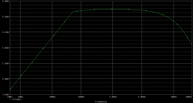
I made an interesting discovery after doing a frequency sweep test in SPICE. The current into the tank seems to drop right below 220 Hz as shown in this graph:

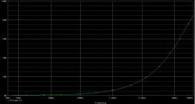
The voltage however shows no dip and increases more or less linearly with frequency. As for the source of this dip in the frequency response I have no idea and tried changing values of a bunch of different caps in the simulation but I can't make it go away nor affect it at all. Anyone know why there would be a current roll off at 220 Hz?
I've also included the graph for voltage:

I made an interesting discovery after doing a frequency sweep test in SPICE. The current into the tank seems to drop right below 220 Hz as shown in this graph:
View attachment 412008
The voltage however shows no dip and increases more or less linearly with frequency. As for the source of this dip in the frequency response I have no idea and tried changing values of a bunch of different caps in the simulation but I can't make it go away nor affect it at all. Anyone know why there would be a current roll off at 220 Hz?
I've also included the graph for voltage:
View attachment 412009
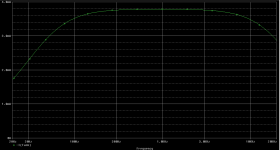
Stupid me! I did a linear sweep instead of a decade sweep. The real graph is more reasonable which would indicate my problem exists only in implementation and not simulation. I'll do more tests and post the results. Here is the real graph:

You are ignoring impedance matching and power transfer.
Per tank data:
No wonder impedance matching and power transfer is awful.
Nothing you do at tube input or biasing will change that.
FWIW Ampeg drives high impedance reverb tanks from triodes loaded with 10K plate resistors, so actual generator impedance lies around 3 or oK ohms, much more reasonable.
And 10X lower than what you have.
Per tank data:
so you are trying to drive a 1475 ohms load from a 36K generator.4 for Type 4
F = 1475 Ohm Input Impedance
No wonder impedance matching and power transfer is awful.
Nothing you do at tube input or biasing will change that.
FWIW Ampeg drives high impedance reverb tanks from triodes loaded with 10K plate resistors, so actual generator impedance lies around 3 or oK ohms, much more reasonable.
And 10X lower than what you have.
An externally hosted image should be here but it was not working when we last tested it.
Mmmh, as far as I remember impedance is specificied at 1kHz but varies proportional to frequency due to dominant inductance.
Having said this, it makes more sense to drive the spring with a more or less current source instead of impedance matching centered around 1 kHz.
I drove my low-input-impedance accutronics with LM380, modified as current source - which worked nice for me.
Having said this, it makes more sense to drive the spring with a more or less current source instead of impedance matching centered around 1 kHz.
I drove my low-input-impedance accutronics with LM380, modified as current source - which worked nice for me.
Hi pgrAm. I am wondering whether you ever came to a conclusion on this 6AU6 reverb driver? I am about to build a stereo reverb unit with exactly them tubes as "current" drivers and I would love to hear any news of how yours turned out 🙂. Before I start pulling my hair out wondering why I aint getting enough 'verb!
Vinny
Vinny
- Status
- Not open for further replies.
- Home
- Live Sound
- Instruments and Amps
- Help with reverb driver circuit
