Ed points to displacement and conduction currents?
Who knows. It wasn't a well formed question.
jn
that it isn't being used
.
Attachments
It does not correctly show the return of the ground sense components on the physical point for best effect. The ground sense and feedback-to-ground components need to be returned physically to the input voltage ground point.
They still mix up (or at least don't make clear) the signal ground and power ground returns. As we say in Netherlands (your nick of the woods Jacco): "they heard the bell, but don't know where the clapper is".
Jan
You mean that there was a double helix on this side? I could have never imagined that but with these guys, you can never tell.😀Somewhere I have an old 3 sides LP of theirs called something like “matching tie and handkerchief”. It was a real surprise when I put the needle down on maybe the 10th playing and then heard a completely new track as it played the second groove on that side.
Side 1: Matching Tie and Handkercief 1 - YouTube
Side 2: Matching Tie and Handkerchief 2 - YouTube
Side 3: Matching Tie and Handkerchief 3 - YouTube
A simple amplifier oscillates …
Than you Mr. Danley for explaining.
There is more than one reasoning behind bursting in oscillation with a multistage amplifier, that’s why I warned for the loose term I used.
My question has to do with the frequency of the oscillation.
I have BBQued some amps but as I was always in the rush to find the ‘Power off’ button for to save the amp and having no storage oscilloscope, I could only have the visual memory from the brief oscillation I saw on the scope screen for to notice the main frequency of oscillation. From this I can say that it was never less than 10MHz.
My question may be rephrased as:
With a certain amplifier that is brought into oscillation, is the oscillation frequency fixed by the design of the amplifier?
I will sacrifice some chip amps to find this out but I would like to read from others here who have kept notes on such unhappy occurrences.

OK
Mainly 1, with some 2. Rarely 3 unless cables are very long.
Thank You. I will try to test No.3
Or was it Nyquist?
Nyquist (criterion)
I think we were putting DC bias (electric attraction) between the two wires of the fig 8 cable.
The signal caused a 2nd harmonic modulation.
I know the ingredients of the experimental jig still exist.
Given a week or two we can revisit what we think we found....mechanical modulation of the pair, causing 2nd harmonic production...or something like that.
Dan.
The electrostatic force between two straight parallel conductors was used for the realisation and dissemination of the Ampere unit on all the National Metrology Labs.
I had seen such a very long set-up, I remember that I was told of measures taken to reduce/damp oscillatory component of the excreted force caused by the restoring mechanical pull-back of the conductors.
So roughly 9 microamps current in the interconnect.
roughly 90uA
George
Last edited:
neck of the woods
The main attraction was the 2009 reference.
Attachments

If an amplifier is unstable only when given a specific load, then most likely it will oscillate at the series resonant frequency of that load, which includes the inductance from the feedback point to the load and the output inductance of the amplifier. The L//R is meant to insert loss in series with the series resonance at the frequencies where it is needed.
It is possible, but highly unlikely to get an amplifier that is stable into any series resonance. Even if you do, RF PSRR combines with rail impedance to make phase margin partly dependent on rail impedance, so you can ruin stability just by adding film bypass caps which become parallel resonators with the lytics.
That said, any good amp will ring (but not oscillate) into a series resonant load. That is normal and expected behavior of a voltage amp and shows that it's working normally. It's better to fix the load rather than the amp.
About the 2nd harmonic with figure-8 cables. Does skin effect cause harmonic distortion or is is it only a time-domain effect? Can it be simulated in time domain reasonably well with a uniform RC line?
I find back EMF servo controlled woofers to sound unnatural Demian, i have not heard the Entec or all servo woofers , but enuff ( velodyne,genesis )to tell electronics at work. I haven't heard any recently, any changes there ...?
Both of the subwoofers you mentioned used accelerometers. There are other technologies. I used a position servo with response to DC. Keith Johnson created the original for a Hollywood project. We then adapted it for consumer audio. I got really tired of consumers wanting to use their favorite tube amp to run it. Woofers with self contained electronics were unknown at the time.
The main attraction was the 2009 reference.
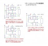
Still no clapper. There are many ground connections in this schematic, and it not at all clear which ones are physically connected where. As an obvious one, the pin 1 of the XLR has the same ground symbol as everything else while everybody knows it should only be connected to the case and nothing else.
Then there's the RCA input ground connection, the output snubber ground, all the supply bypass element grounds, the feedback grounds etc. The main power supply ground isn't even shown. It is no wonder that many of these attemps to remote sensing oscillate or give bad results.
If you want to use it, you need to design your amp from the ground up (no pun intended) with this in mind. Connect power supply return at the speaker return. Connect the remote sense ground wire to all feedback grounds and the input signal ground wire (if unbalanced in). Keep all power supply and bypass grounds seperate from that. Etc.
Jan
Last edited:
If an amplifier is unstable only...
Thanks a lot for this informative answer keantoken
it will oscillate at the series resonant frequency of that load, which includes the inductance from the feedback point to the load and the output inductance of the amplifier.
Well, here is some meat.
While trying to measure the output impedance of some amplifies by injecting HF at the speaker-out terminals of their enclosures, I found out that what I was measuring from ~200kHz and above was actually the impedance of the wiring from the speaker terminals to the A-B switches to the amp PCB.
Tens of Ohm plus some.
Repeating the measurements on mock-ups of such wiring schemes with a solder short at the end confirmed the scenario.
This can be a factor with the stability of an amplifier to the extent that it is sensitive to the ingress of RF trash through the back door.
An RF shunt capacitor across Speaker-Out terminals will not work effectively, it may make the situation worse in some cases.
Internal rewiring is the remedy but if this is not an option, RF dissipative elements should be placed around the speaker wires as close to the amp PCB as possible.
Ferrite beads (trial and error) or this custom trimmable diy offering by Ed: http://www.diyaudio.com/forums/everything-else/172673-bybee-quantum-purifier-measurement-analysis-131.html#post2447472
Read posts #1301, 1302, 1303, 1304, 1305, 1306, 1324, 1327, 1335, 1357, 1367
Jan’s post is relevant
Some may be interested in the X2Y caps. Scan through their Technical Library:
X2Y Attenuators - Home
Who knows. It wasn't a well formed question.
Wait till you see the answer.
I feel a trembling every time Ed writes “this is a simple question for the peanut gallery” 🙂
George
the impedance of the wiring from the speaker terminals to the A-B switches to the amp PCB. Tens of Ohm plus some.
This can be a factor with the stability of an amplifier to the extent that it is sensitive to the ingress of RF trash through the back door.
George
George, one could also argue that the hf impedance from connector to the board etc prevents hf ingress to some extent. Sort of the output inductor, but unrolled.
Jan
Your question is phrased oddly. Skin effect is the nom de plume of the reaction of the current within a conductor to the magnetic field produced by that current in that conductor. The time varying magnetic field creates toroidal eddy currents in a cylindrical conductor, and these counter the transport current which is causing the magnetic field. This moves the current density towards the outer part of the cylinder, and it is an effect which is related to the absolute value ABS() of the rate of change, a doubling of frequency as it were.About the 2nd harmonic with figure-8 cables. Does skin effect cause harmonic distortion or is is it only a time-domain effect?
Proximity effect is the generic nom de plume for current redistribution as a result of externally generated time varying magnetic fields. When the other conductor is carrying the exact same current but in the other direction, it too will effect redistribution as a function of double the frequency as a result of the ABS() function of the effect.
Both are a consequence of eddies.
No. An RC model contains only linear elements.Can it be simulated in time domain reasonably well with a uniform RC line?
jn
Almost there. Current density and charge interaction is the issue. Electron drift ain't it.
Now does anyone want to discuss how Ohm came up with his equation?
Ohm's law can be derived from first principles, it is a major section of several graduate courses. There are several other ways to derive it. I thought you didn't believe in it anyway. As jn said the question is poorly formed.
All Cables Sound The Same....???.
Dan.
So, the cable effects you describe, in combination with effects of cable dielectrics (insulations) and amplifier load dependency characteristics combined with loudspeaker impedance characteristics may give rise to the notion that differing loudspeaker cables may cause differing subjective resultants ?.Your question is phrased oddly. Skin effect is the nom de plume of the reaction of the current within a conductor to the magnetic field produced by that current in that conductor. The time varying magnetic field creates toroidal eddy currents in a cylindrical conductor, and these counter the transport current which is causing the magnetic field. This moves the current density towards the outer part of the cylinder, and it is an effect which is related to the absolute value ABS() of the rate of change, a doubling of frequency as it were.
Proximity effect is the generic nom de plume for current redistribution as a result of externally generated time varying magnetic fields. When the other conductor is carrying the exact same current but in the other direction, it too will effect redistribution as a function of double the frequency as a result of the ABS() function of the effect.
Both are a consequence of eddies.
jn
Dan.
I cannot state that they produce audible results.So, the cable effects you describe, in combination with effects of cable dielectrics (insulations) and amplifier load dependency characteristics combined with loudspeaker impedance characteristics may give rise to the notion that differing loudspeaker cables may cause differing subjective resultants ?.
Dan.
But
I can say that the effects cannot be dismissed casually as being of no concern. My concern would be the actual level of effect. Just because the effects exist doesn't mean they always impact the system at a level high enough to be audible. If the effect is an order of magnitude or more below human discernment, they can be dismissed with little worry.
Ed's 400 feet of #10AWG vs 400 feet of #14 into a tweeter comes to mind. While some may come away believing that skin effect was the culprit, there are many more variables in the equation.
If it had been me, I would have done a few tests on the in situ 10 gauge, then after replacing it with #14, re-do the tests.
I would have run a scan of Ls/Rs/Cs on the cable while shorted at the tweeter. The line impedance may have been the issue (settling time), the cable inductance(Ls), the cable capacitance(Cs), proximity to metallic surfaces such as conduit (Ls/Rs), self induced proximity (Ls/Rs).
Without performing the proper tests, it is impossible to determine what the actual cause was. Reporting the issue is only the start of the investigation.
jn
JN,
Without knowing anything about the cable that Simon used for those tweeters but the length being 400 feet each direction could I somewhat assume that the 10 gauge would have had lower dc resistance but possibly higher C,L thereby either could have been an added series or parallel element added as a passive low pass element affecting the high frequency limit? This is leaving out any proximity effects of any metal support, let's say hanging in air.
Without knowing anything about the cable that Simon used for those tweeters but the length being 400 feet each direction could I somewhat assume that the 10 gauge would have had lower dc resistance but possibly higher C,L thereby either could have been an added series or parallel element added as a passive low pass element affecting the high frequency limit? This is leaving out any proximity effects of any metal support, let's say hanging in air.
- Status
- Not open for further replies.
- Home
- Member Areas
- The Lounge
- John Curl's Blowtorch preamplifier part II