My ITT HiFi8011 direct drive turntable has terrible wow and flutter. The dots on the strobe wobbles back and forth, and the 1khz sound on my test disc is all over the place.
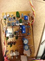
Knowing that wow and flutter on a direct drive is usually caused by faulty caps I replaced all electrolytics and all resistors, even the two op-amps. Didn't help. According to the manual, there are 3 variable resistors responsible for stabling the motor, but all the manual says is "adjust for minimum flutter and wow (≥ 0.12% according to DIN) with trimmer resistors VR 03, VR 04 and VR 05".
Turning these resistors seems to have little effect other than at the lowest and highest resistances, which makes the wobbling worse. I've also replaced VR03 and VR04, but it didn't help. Does anyone know if there are any voltages or resistance I can read on a DMM while turning the resistors? Twisting them back and forth blindly is obviously not the way to do it..
I've also lubed the motor with light viscocity oil, but I have a feeling this is a circuit board problem...
Attachments
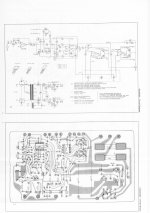
It would be best to borrow a dual beam oscilloscope and obtain a service manual as a pre-caution. Briefly the adjustment procedure to follow ;with the c.r.o probes attached to the motor connection points 10 and 11,the pots VR03 and VR04 are set to give an equal voltage of approximately 5V (p to p). The other adjustment for VR305 is for setting the phase difference to 90 degrees. VR04 may require resetting after this adjustment.If there is a fault that is not fixable by adjustment then it will be most likely be the 2SD468/2SB562 drivers or the NJM 4558 I.C.
It would be best to borrow a dual beam oscilloscope and obtain a service manual as a pre-caution. Briefly the adjustment procedure to follow ;with the c.r.o probes attached to the motor connection points 10 and 11,the pots VR03 and VR04 are set to give an equal voltage of approximately 5V (p to p). The other adjustment for VR305 is for setting the phase difference to 90 degrees. VR04 may require resetting after this adjustment.If there is a fault that is not fixable by adjustment then it will be most likely be the 2SD468/2SB562 drivers or the NJM 4558 I.C.
Thank you for the advise. I tried adjusting VR03 and VR04 using a DMM, and the voltages where indeed non-adjustable and a bit fluctuating at around 4 volts. Not sure if the voltages are supposed to be rock steady though. I have replaced the NJMs, and might try to get a hold of the transistors.
What do you mean with "p to p"? I would not know how to use an oscilloscope, so adjusting the phase difference to 90 degrees is out of my league. If it doesn't clear up I'll deliver it to a tech, although I'm not sure if my turntable is basically a piece of crap. I have not found any info on the "ITT" brand anywhere.
' p to p ' = Peak to Peak voltage wen viewed on a scope.
Is that circle with a G in it a speed sensor? A poor or intermittent speed signal could cause your problem. Same with its high gain preamp Z01A. How about checking C01 and C05? old dried out electrolytic caps cold cause problems too.
Is that circle with a G in it a speed sensor? A poor or intermittent speed signal could cause your problem. Same with its high gain preamp Z01A. How about checking C01 and C05? old dried out electrolytic caps cold cause problems too.
It's hard to troubleshoot something like this without a scope. You need one so you can look at the tachometer 'G' waveform, then the high order LPF filter output and so forth. A DVM with a frequency might help in confirming the presence of the tach signal which is used to regulate the speed. Without the tach signal your TT is running open loop with no speed regulation.
There's only 8 BJT transistor, the 2 pass transistors on the regulator are easy to check in circuit, i.e. there is regulation or none. The ones that are driving the motors are potential suspect as they are used as linear devices and can dissipate a lot of heat during operation and loose gain over time. 2SD468/2SB562 are rated for 20V. I'm curious if there is enough voltage to kill these when the platter is rotated without power. Ideally, fast diodes should be placed across the C-E of Q4-Q7 to protect them. Cheap design.
I've seen transistors that pass the usual DVM diode test but have no gain when popped into a curve tracer
You also have what appear to be a Hall effect sensor below Q5 on the schematic. A scope will show you if there is switching happening on its outputs when the magnet passes one of its flat side.
- Status
- Not open for further replies.